- Home
- About Us
- Join/Renew
- Member Benefits
- Member Pages
- Log In
- Help
- Museum Store
I have removed the tank to clean and would appreciate information on all 4 lines leading from tank.
Dad had tried to solve a fuel delivery problem, but it has not yet been resolved so that is why I removed the tank.
There seems to me to be too many lines.
I appreciate any input on this.
Thanks
Jim
Do you have a picture? The standard lines on my 35 are basically 3 coming out the top through the fitting screwed on top that holds the King Seeley fuel gauge sending unit in the tank. Coming out of the top of that fitting is the fuel feed tube attaching to the 5/16 tubing going to the carb, the, the tube with a fitting to attach the tiny copper tube that goes up to the KS gauge on the dash, and a vent tube for the sending unit that bends back towards the tank is isn’t attached to anything. That’s 3. There is a fitting on top of the tank above the filler tube for a copper line that runs up to the top of the filler tube to allow the tank to be filled to the tip without an air lock. That’s the four I can think of, at least for my 35 sedan. Does yours have more than these?
I now believe that the main problem that caused the recurring clogging of fuel filter is that someone connected the fuel supply line to the bottom
of the tank where the drain plug should be. So now hope to get better service by cleaning and also not feeding from bottom where what sediment remains will fall.
Interesting. The normal pick up tube coming from above goes very close to the bottom so can still pick up crud but not as bad as it just dropping into a bottom hole. I din’t believe I could ever get my tank 100% clean without cutting it open, and on another car sloshed gas tank sealer which became a bigger problem than the crud. My ’60’s cars have a filter screen on the pick up tube, but of course on of the problems with a screen on a pickup tube mounted on top of the tank is getting it out to clean if it plugs up.
If my car ever comes back from the upholstery shop I have been thinking of modifying the fuel system. Normally it will use the original mechanical pump drawing from the original pickup tube, but the the auxiliary electric pump system will draw from the bottom drain fitting and have some recirculation up to the carb to cool fuel system and return hot fuel and vapor to the tank. This to fight vapor lock problems. It would return the excess fuel via the original pickup tube flowing in reverse to backflush the pickup tube. I think I can arrange a small vertical screen going up into the bottom drain fitting to keep the big chunks out and then a good sized transparent water separating filter to catch the fine particles before going to the electric. Being on the bottom the small diameter screen going up through the bottom is accessible to remove and clean and it is only operated occasionally when the electric is on. It will go several inches up into the tank so it still can get fueling the bottom of the screen gets plugged with crud. The idea being I have two redundant fuel pickups. How’s that for overkill? I am paranoid of an engine dying on a hot day sitting in the left turn traffic lane in heavy traffic with a 5500 lb car.
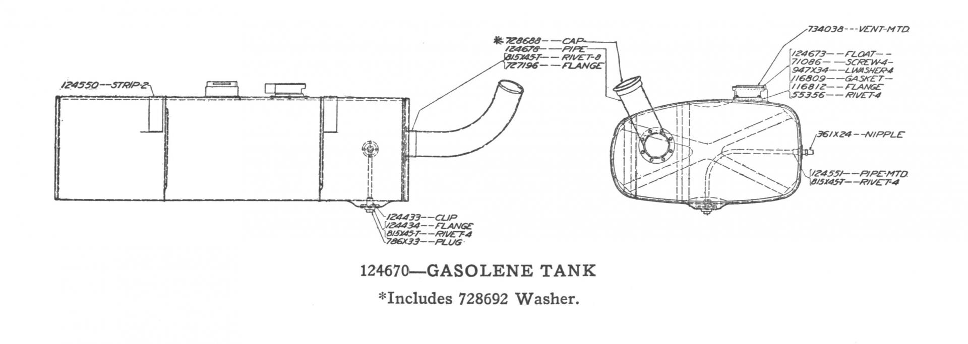
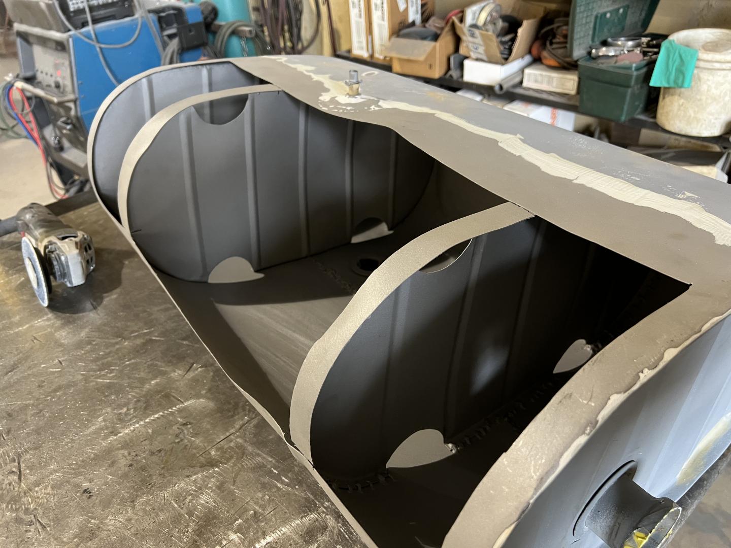
Are there any known drawings of the mid 1930’s gas tank? Has any member had their tank interior cleaned? How? Does the tank have to be cut open? I presume there are baffles inside. The factory must have had drawings. Has anyone used a “bore-scope” or are internal baffles in the way for a good look?
This is out of the 1930 Parts Book, the last one with drawings. I don’t know if it will help you or not. As far as a Borescope, you can pick one up at Harbor Freight for $60-70.
 .
.
On my ‘34 840A I had a damages gas tank and had to have it repaired. The picture shows the tank inverted and you can see how it is structured on the inside. 
Where can I find fittings for 5/16 copper tubing. Thanks
Glenn,
I would think most fittings are available at your local hardware store. If not, try Mcmaster Carr: https://www.mcmaster.com
Is there something in particular you can’t find?
Dave
