- Home
- About Us
- Join/Renew
- Member Benefits
- Member Pages
- Log In
- Help
- Museum Store
Tagged: generator, voltage regulator
Good Evening,
My 1936 1602 V12 is now running, but the battery does not charge. Basic information follows:
Per a recent PAS technical article about the Startix system, the Startix appears to be wired as intended, with the large wire from the generator connected to the battery at the Startix, and the small generator wire (field?) connected to a small post on the bottom of the Startix. I am suspicious that the Startix is not exciting the field to allow the generator to produce current. Initially, I would like to test the generator while mounted and being run on the engine. I have a basic understanding of how to test automobile generators, however I am not familiar of what to expect to see as output when energizing the field on this positive ground system. I would appreciate assistance with a couple of very basic questions. For purposes of responding, assume that the generator is being run slightly off-idle and both wires are disconnected from the car.
I was told by the previous custodian of this car that the voltage regulator was faulty and has been replaced. I was expecting to find the voltage regulator on the cowl, but do not see one. This leads to another couple of questions:
Thank you in advance for your time and assistance,
Jon B Kanas
Email: [email protected]
Website: http://www.2experts.org
Longmont, Colorado; Cultural Center of the Universe
John,
Your 1602 has a 3-brush type generator with a cutout relay AND a voltage regulator. Look at the wiring diagram on page 90 of the Pierce Arrow Wiring and Tune-Up Guide (published by PAS) This is a very good reference. See PAS Service Bulletin 89-#1 for a short explanation of this regulator; “Hollander parts interchange manual lists the original relay-regulator unit used on Pierce- Arrows from mid-year 1935 models on, as an Autolite #40300, used on no other automobile vehicles.”
This diagram does show a field fuse in the regulator, which could cause some of the trouble you describe. Another problem could be the loss of residual magnetism in the field iron, which happens after sitting for several years – the remedy is to flash the field coil with battery voltage for a very few seconds to restore this residual magnetism.
My 1943 Motors Manual confirms that 35-38 Pierce did use the Startix and a 3-brush generator. The third brush set the output voltage of the generator and is typically adjustable around the armature to make this happen. The generator section does explain that (1) polarity does matter to the voltage regulator, (2) there are several types of regulators used on cars of this vintage (A) Light switch controlled step voltage, (B) two step relay control and (3) vibrating regulator, which rapidly steps the output up-and-down in response to battery voltage.
A quick search of the internet DID turn up a mechanical voltage regulator with positive ground that should work to confirm your system: The Ford 8N & 9N from about 1950 have this system and the regulator is still available from antique tractor supply houses. Not a perfect fit, but probably better than nothing to prove if your regulator is the problem.
The cutout relay is the other issue and that can be investigated by removing the cover and verifying that the coil is a complete circuit and the contact arm is free to move. Some people change this out to a large diode hidden in the original enclosure, but should not really be necessary.
Hope this is helpful
Good Evening Herbert,
Thank you for your prompt and informative response. I’ve done some additional research per your response; I remain confused about the voltage regulator. From Technical Bulletin 1971-5 I note “the Generator Control Unit relay regulator is a Delco Remy 40300, mounted in a single case on the generator field frame”. In Technical Bulletin 1989-1 and in your response to my initial post, you advise an Autolite 40300 regulator and a later technical bulletin refers to the regulator as a Owen_Dynetto 40300. Is it possible for you to confirm the appropriate brand for the regulator? I, also, have an old Motor’s manual, however it does not provide any manufacturer information for either the generator or regulator.
I have no visible regulator mounted to the Generator; Both wires from the generator appear to go to the Startix. The large wire connecting to the battery connection on the Startix and the small wire to the field connection. Do you have any suggestions where a likely mounting point for the regulator would be found? This car is a prize winning restoration, and I really want to minimize the potential of damaging items while hunting for the regulator.
I have seen references to the use of both Owen-Dyneto and Delco-Remy generators in the Pierce Arrow. I have been unable to identify the manufacturer of the generator in my 1602. Service Bulletin 1998-3 indicates that the 1602 would have been equipped with an Owen Dyneto generator and a 40300 regulator, no mention of Delco. Can you provide me with any guidance to identify the Generator manufacturer based on the physical appearance of the generator? I, too, have an early Motor’s manual but it does not identify the Generator manufacturer.
Thank you in advance,
Jon Kanas ([email protected])
Jon, this will be but little help: Autolite acquired Owen Dyneto in the late 1930s but seems to have maintained the Dyneto part numbers. An Autolite-branded 40300 will serve just fine, as it’s the identical piece of equipment. Actually, in mid-1934, Pierce began using Dyneto starters and generators, replacing Delco-Remy units, but there are some original 1935 Pierces which had Delco equipment from the factory, including Paul Johnson’s very original model 845.
The regulators on 1936-38 Pierces remained atop the generator. I’m thinking that someone substituted a 3-stage regulator for the Dyneto, and mounted it on the firewall as is the custom for virtually all 3-stage regulators. I think you need to look at a wiring diagram and trace everything out. Which generator (Dyneto 3-brush?) do you have? Or did some previous owner convert the generator to a later 2-brush system in conjunction with the installation of the 3-stage regulator? That is, a holistic approach to the charging system (generator and regulator) is required, including an analysis of existing wiring against the factory diagram.
And do you still have the Startix? That unit senses a lack of signal from the generator and automatically engages the starter–to respond to a stall.
Take George’s advice as he has much more experience with this generation of cars than I do. However, the PAS Wiring and Tune-up guide does have some good advice (as does some older Service Bulletins on this site). It appears that 1935 was the first year of the voltage regulator, and it was installed as part of a single unit with the cut-out relay and mounted on the generator. The function of the cut-out relay is to prevent the generator from acting as a motor when the engine is off. If this relay fails, the generator will drain the battery in a very few hours, as the locked rotor current draws about 18 amps. I did find a picture of a ’35 with a single unit mounted on the generator, where the Wiring Guide says it should be (picture did not load – I will email it to you separately).
One way you may be able to distinguish between the Delco and Owen-Dyneto is by the number of field coils used. Each field coil is held in place by a large screw through the case of the generator. According to the Wiring Guide, the Delco unit uses only two field coils (and therefore 2 screws), while the Owen unit uses 4 field coils and thus 4 field mounting screws.
The wiring diagram and text on page 89 (for all the ’36, 37 & 38 models) mentions a 5 amp fuse mounted in the voltage regulator case (under a knurled plug), to limit field current. If this fuse is blown, then the generator will have no output. This would be the first item to check. The regulator is a 2-step type that apparently should shift at 8 volts / 1900 rpm / about 25-30 mph.
For many years NAPA sold a regulator VR755 that was used by many mid ’30’s classics as a universal substitute for the wide range of regulators used on those cars. It mounts to the generator as original. Unfortunately they stopped producing them a few years ago and they are very hard to find now – a lot of people bought spares. That specific regulator was originally used on some models of ’35-36 Chrysler products. It does not have the extra gen lead sticking out the side to connect the startix (it was optional on Packard), but the gen connection is made under the regulator so I think the extra connection could be made there. I have a generator with regulator from a ’33 or ’34 Packard that looks identical to my ’35 Pierce unit including the hookups, although the internals are actually a bit different. It would probably work, but much harder to find than VR755.
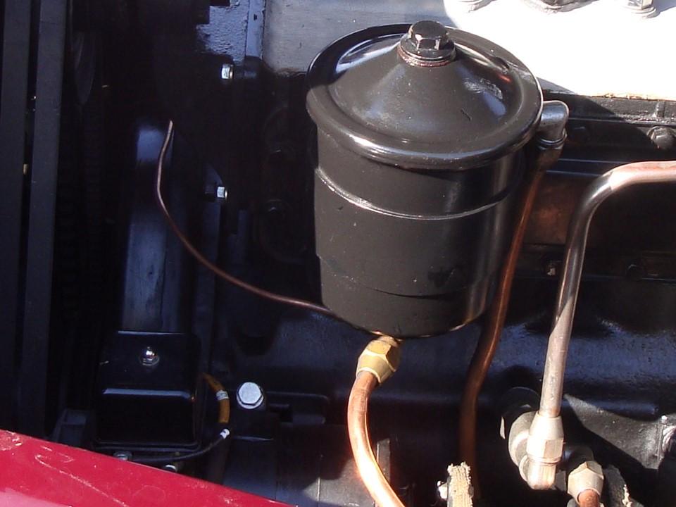
The picture is one I took of a ’36 Pierce which appears to have a NAPA VR755 regulator attached to the top of the generator, the tell tale being the nut on top of the can.
Gentlemen,
Thanks to all for your assistance to date. I’ve made some progress this evening. I have a diagnostic question, additional observations and some images of what I’m dealing with.
Diagnostic Question: I would like to determine if the generator works at all. I think my next steps are to disconnect it, then touch a wire from the chassis to the field post to see if I can excite the field enough to detect voltage from the armature post using my VOM when the engine is running. I would appreciate any thoughts about whether or not this approach can determine if the generator is operational.
Regulators: The prior custodian of this car had replaced the voltage regulator / cut-out in an unsuccessful attempt to resolve the charging issue. He provided me with the regulator he removed as faulty. It contains a stamped identifier “2110 6V Pos” on its chassis, clearly it is some type of replacement. The cutout points are severely heat discolored with very little gap. They appear to be salvageable with judicious application of a points file. All of the coils test OK for continuity with a VOM.
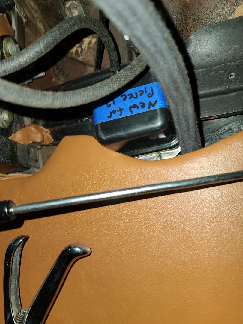
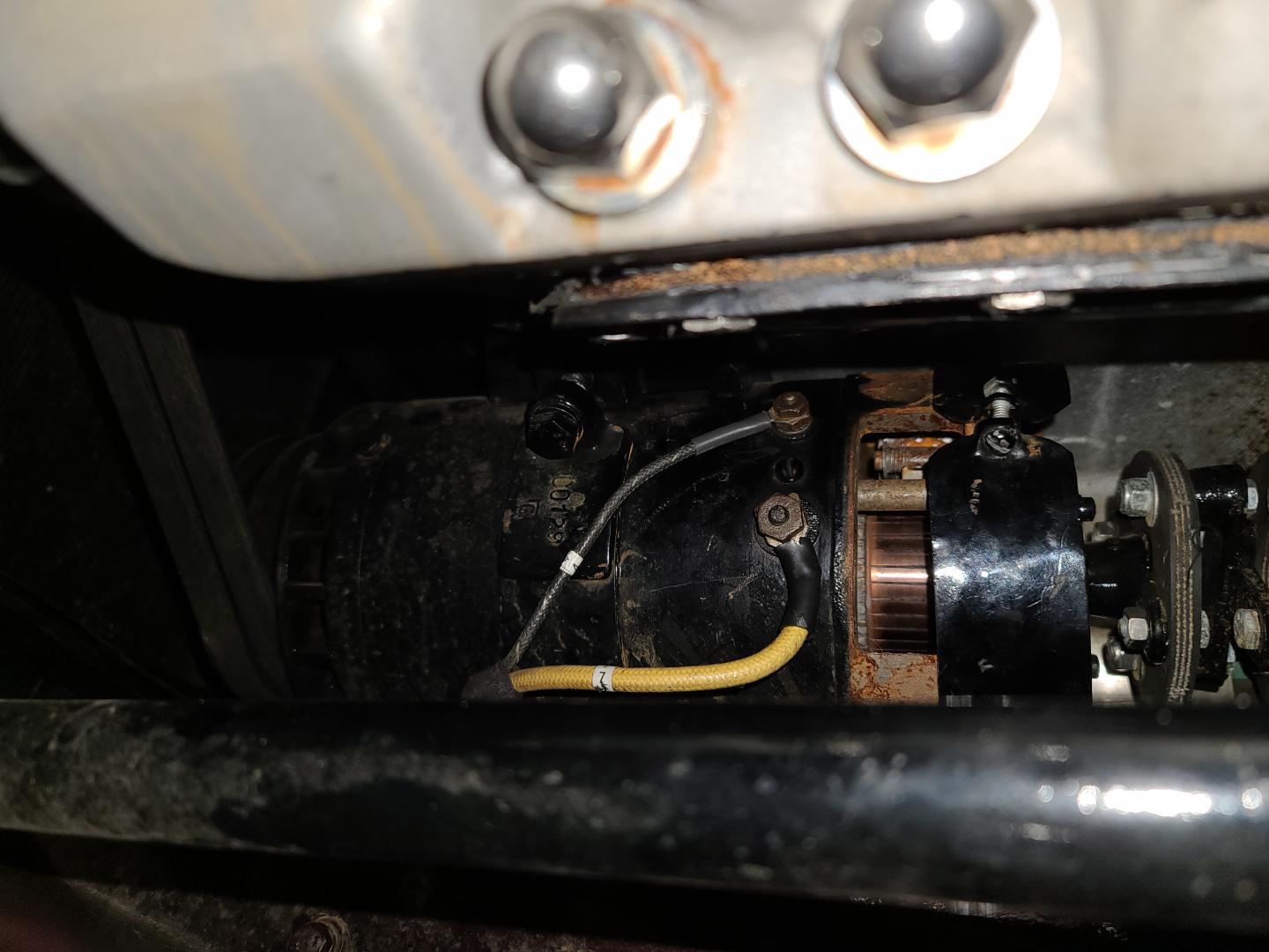
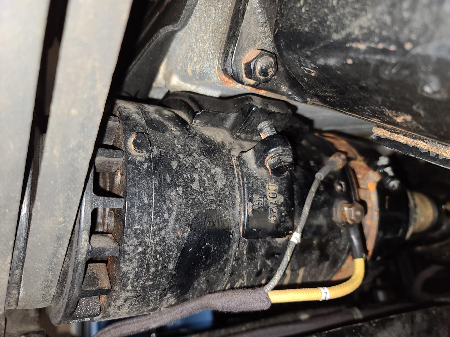
Tonight, after a considerable search, I located the voltage regulator under the dashboard along the left cowl, above the parking brake. Now that I’ve found it, it looks like my next steps are to dismount it and trace the 3 wires and see how this has been wired into the charging and Startix circuits. Following is an image where I found the regulator, and a couple of images of the generator if anyone can identify it.


Thanks to all for your ongoing assistance.
Jon Kanas ([email protected])
The first time my Packard quit charging (with basically the same 3rd brush setup and regulator as Pierce) it was the regulator, the second time a few years ago it was simply the 3rd brush was worn out. They are easier to find than regulators if that is the case.
If I remember right it was a bit iffy to diagnose statically, testing it would show continuity statically. Good luck.
Jon, remember that you have to have some rpm to get a charge showing. Factory wiring requires a signal from the generator to prevent the Startix from engaging, but I don’t know how little output will accomplish this. The best news in your photo is that you seem to have a fairly fresh wiring harness with readable color coding! That square (2-stage) regulator appears to be the proper type for your car.
If the car were mine, I’d pull the generator and have an electrical shop confirm that it is indeed capable of producing a sufficient charge.
To make better sense of wiring diagrams, I recommend taking a wiring diagram to a print/copy shop and have 6 or so enlargements made to 11 x 17 inches. And buy a pack of 4 to 6 different colored highlighters. Use one copy for charging, one for lights, etc. as you wish, and highlight individual wire traces with different colors.
Good Evening George et al,
Herbert Tull noted in an earlier post the Pierce Arrow Wiring and Tune-Up Guide from PAS. I could not find this manual on the site, and would like to order / purchase one. Any hints about where to find this, or ordering would be appreciated.
This car starts easily, and the hand throttle is operable, therefore I thought is to use the hand throttle to hold the engine a bit higher than idle, then energize the field winding and watch the voltage at the armature wire. At this point, my objective is to observe whether or not the generator is capable of producing current.
The Startix is a potential player here, too. It looks like the two wires at the generator both go to the Startix, one to the main battery connection and one to a terminal on the top of the Startix. If the Startix has a problem that is grounding the field signal, that could prevent the generator from producing current. There are lots of variables here, and I’m attempting to address them one at a time. I’d be much happier if I were confident that the generator works while I go through the other elements of the charging system. Now that I’ve found the regulator, I can do a wire trace and see how these components talk to each other.
Wiring: This car is a CCCA award winning restoration from 1999 and appears to have had only 450 miles put on it since the restoration. Everything is in excellent condition, making me very hesitant to remove the generator for testing as I am likely to scratch or injure something in the process. The wiring harness is marked like the harness I purchased from Y&Z for my Buick, complete with identification numbers near the ends of each wire. I contacted Y&Z to see if they will sell me one of their installation guides that identifies their numbering scheme for this car. These guides also suffice as a wiring diagram that is component based.
It’s gotten cold here today, and I have a tight work schedule for the rest of the week, so any further activity will have to wait for a few days.
Thanks again to everyone for their interest and suggestions!!
Jon Kanas
HA! Found the Pierce Arrow Wiring and Tune-Up Guide on the site. Ordering it now.
I went through the same experience with my 36 several years ago. Problem was an improper regulator. A universal regulator will burn up you generator. Regulators are either A circuit or B circuit. I found the proper regulator at Steiner antique tractor parts. I charge at 7.1 volts with lights on at fast idle. Voltage output can be set while car is running. Amperage is set by moving the third brush. I f you want the info I can dig out the proper part number. Call me at 479 414 6107 if you need the info. I was in the dark for so long and even generator people didn’t know. All the people who knew this stuff in the day have been dead for 50 years. Regulator was about $40. This will fix it if generator is charging.
Follow-Up; Better late than never
Not too long after this thread, I did manage to do a test on the generator (car running, generator not electrically connected). If I stimulated the field the generator produces current, but appears to be polarized wrong. I can read voltage from the generator on my analog multimeter as if the car is negative ground. When using a digital multimeter, it acted almost as if the voltage coming out of the generator was AC, not DC; The reading did not make sense. Not long thereafter I got into a lengthy project rebuilding the tailgate on my Packard Station Sedan, so no further work has taken place on the Pierce.
I am just now getting back to the Pierce. I was never able to determine what unidentified generator is installed on this car, therefore could not determine if “A” or “B” architecture for polarizing. After some lengthy discussions with a couple of AACA folks, I am now thinking that the generator may be out of a Seagraves fire truck. In any case, I have given up trying to polarize / repair the generator myself, and the car is going to a restoration shop I trust next week to address the charging issue, and undo some very creative wiring that the previous owner had installed to feed 12V to the starter while circumventing (and maybe destroying) the Startix.
