- Home
- About Us
- Join/Renew
- Member Benefits
- Member Pages
- Log In
- Help
- Museum Store
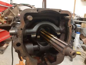
Forgot, you have to lift the lock plate so that the shaft will go in. The flat grooves on the shaft serve to locate the lock plate. When you shift to 2/3 the end of the shifter ball lifts the plate and allows the forks to move
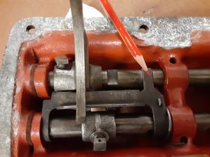
Tighten the locating pins with a 3/8″ open end wrench then safety wire them.
You may have to loosen the screw to get the wire in then tighten it. I use stainless wire.”
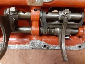
I bought new 3/8″ ball bearings to replace the old detent balls that had worn. Insert greased ball in the side hole then the spring then the plug. I pulled the spring out a little to compensate for wear. Do the same on the other side. Need to have the rails in the neutral position.”
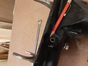
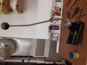
Flip it over and grease the shifter socket and install shifter, spring concaved washer and screw on the retaining color. Insert reverse switch pin and you are done with the cover.
Bill,
Showing detail pictures of a project like this is a really valuable gift to our members. Many thanks for doing this and setting an example for others to follow in the future.
Dave Stevens
Due to the size/weight I decided to use an engine stand.
Needed an engine hoist to get it on.
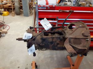
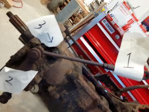
Here are the key external operating rods.
1. Handbrake
2. Yoke to actuate(pull) the front and rear brake cables
3. Speedo input
The rear cover, bearing/spacer, friction plate and movable brake plate have been removed
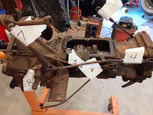
And here is the left side
4.brake actuating rod to brake cable yokes
5.Freewheeling lever ???, someone verify please.
6.I have no clue, What is it?
7.Brake pedal
8. Clutch linkage without pedal
Looks like you may have pitting on gears in the trans. The gears are only case hardened and will tear themselves up if they are pitted. Usually the input shaft is the biggest issue…….looks like you unit sat exposed outside, and it may be worth the effort to locate another unit.
#6 the rod attaches to the arm of the clutch pedal.
Ed,
You make a valid point. When I used to own 3 transmissions businesses, we always had concerns over tooth pitting. This trans has been inside for 60 years and the top has been on it for 58 of them. I took the cover off a couple of years ago to look at tooth condition, chips, rust, etc. I think these are ok with just surface, not pitting rust, but I will know more when I get it apart. Might need a 2/3 gear, we will see.
As Ed suggested, you won’t like the noise if the gears are pitted.
David,
How does it attach to the clutch and what does it do? With a clevis pin??
Bill
Bill…….FYI……..every year Pierce made changes to the internal parts of the transmissions…….thus the gears are not interchangeable across the board. Pierce was also famous for shipping experimental gear designs out into the field to see how they held up. I ended up with one of these experimental units……..it looked like nothing I had ever seen as far as gear design. It functioned well……….but when you open up a Pierce transmission all rules go out the window as far as parts replacement. I have made fears in the past, but today single gears can easily cost two grand…….and a good used transmission can usually be had for half of that or less.
Bill. Here are some pictures I took in 2003 of my 1935 845 before I disassembled. I have many more, thanks to one of the great boons to restoration – digital cameras. I can forward some via email if needed.
I think your 1933 should be about the same. Yes, Number 6 attached to the clutch pedal it is involved in the free wheeling operation. Note the springs involved in the connection. Don’t remember how it all works but was obvious when working the unit when reassembling. Yes, number 5 attaches to the freewheeling cable control.
The brake unit is an interesting piece!
Jim
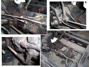
Jim,
Thanks for the photos. Ok, here is what am thinking. there are two controls to the left rear of the case, the freewheeling cable and the rod that is off the clutch pedal.
If you are in freewheeling you can shift without depressing the clutch so the freewheeling lever unlocks what the rod off the clutch does when you are not in freewheeling. To be able to shift at all, there must be something that the FW or the clutch pedal rod releases.
I am sure there are people that know how this works, but that is my best guess.
It’s a simple and elegant design…………and it works great………
Now it is getting interesting, I removed the end case, brake clutch, movable clutch plate and got to this.
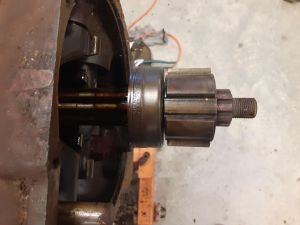
This is the hub that the clutch disc slides on (splined).
Happens that this splined hub rides on a spiral Bendix similar to a starter.
Haven’t figured how it works yet but I will keep dismantling.
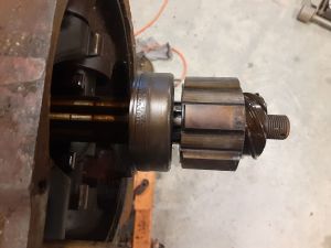
So, it allows the clutch to advance even if the shaft isn’t turning, so conversely it must mean that the shaft can continue to turn even if the brake clutch is engaged, otherwise it would kill the engine. I think???
Next is the 2 forks that can activate the brake clutch.
Next on the shaft is the speedo drive gear/shaft, which I will have to figure out how to remove
