- Home
- About Us
- Join/Renew
- Member Benefits
- Member Pages
- Log In
- Help
- Museum Store
Being basically lazy, I wanted to make valve grinding more mechanical and I came up with this setup.
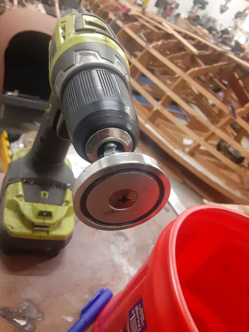
I used a neodymium 70#, 1.65″OD countersunk magnet, a 1/4″ machine screw and a 1/4″ all thread coupler.
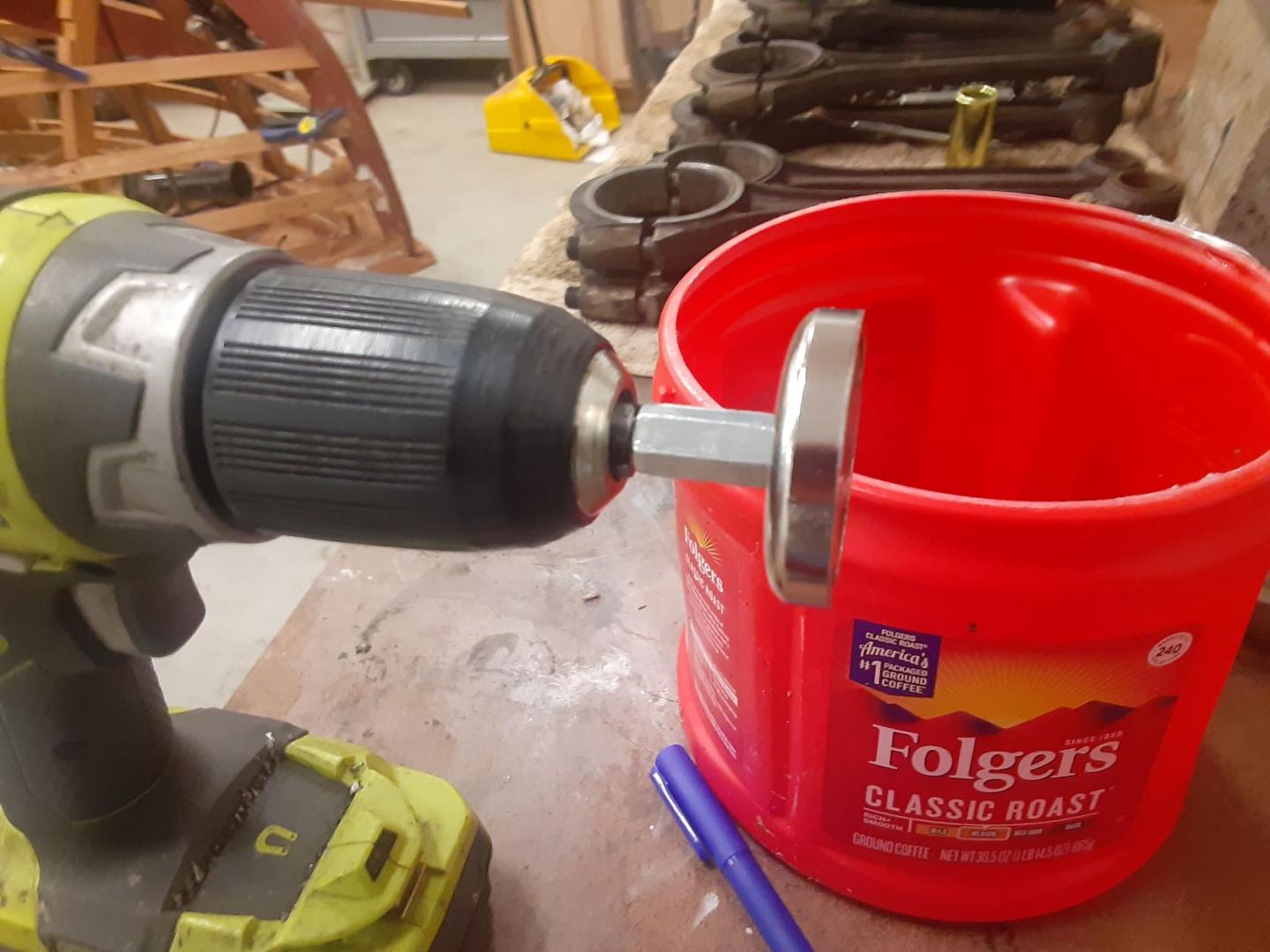
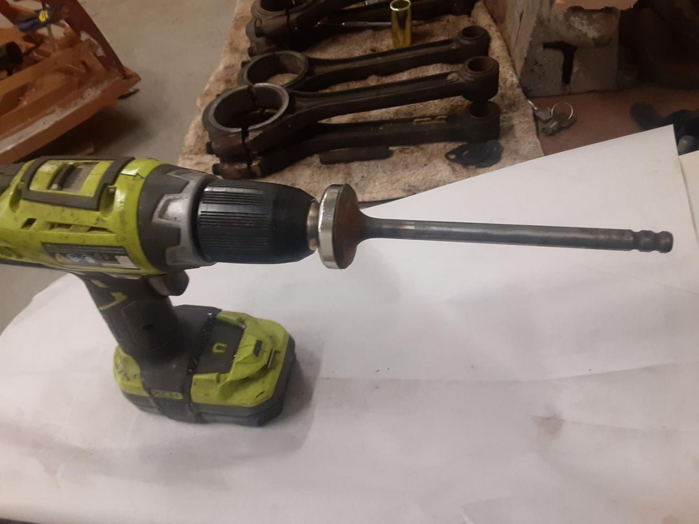
The valve is attracted to the magnet (it is very hard to remove it from the magnet) and you can reverse and use variable speed. It won’t work with stainless valves however. Put valve compound on the valve face, oil the stem, insert it in the block and grind away.
Hi Bill, while that is an interesting idea, I highly recommend that you do not use that method..
One important reason is that the way you find out if your valve is actually touching the seat in the engine block is to do a quick few strokes of the valve with grinding compound on the end of a suction cup stick. The back and forth motion keeps the valve in the same position on the seat. The old valve lapping machines had a back and forth motion because this is the best way to lap a valve into a seat. Then a bright light and sometimes a magnifying glass is used to see the dull finish that the grinding compound left behind..
What often happens is that a seat wears off center from the centerline of the valve guide.. The seat can even be oval instead of round.. So the dull grey spots show the contact areas, the still-shiny spots are where the valve is not yet touching the seat. And a valve seat can be not-concentric with the valve stem.. This shows as only a portion of the valve having a dull contact area..
When a motorized valve lapping setup is used like you propose, then you run the grinding compound all the way around, it dulls the entire seat, leaving you to believe that the valve and seat are actually touching and sealing all the way around.. But there is no way to know if it actually is touching and sealing
The next problem is that this power lapping will make the seat and contact of the valve rounded, which does not seal well, or conduct heat well. The half-round groove cut by power-lapping makes the valve have a narrow lip, or outer margin. This then gets hot very easily on exhaust valves, which then erode and split and leak.
A correct valve seat for our Pierces is a 45* seat that for intake valves is around .040″-.060* wide. For the exhaust valves around .070″-.090″ wide. A slight cut to take the sharp bottom edge off of the 45* seat using a 60*or 75* cutter and also for the top edge of the seat a 30* cutter is used to take the sharp edge off the 45* seat.
It is crucial for a valve to contact the cooler engine block with a good heat conducting contact area, this is why the exhaust seats are wider to aid in conducting the heat from the very hot exhaust valves. A rounded seat will also trap carbon particles and then leak much easier than a crisp 45* seat.
I ONLY use grinding compound to do a very light touch-lapping of a valve to it’s seat to look and see that the machined, cut, or ground valve seat and engine block seat are concentric and making contact all the way around.
The lapping process was used in the days when we had tons of carbon in the combustion chamber from oil getting past the rings, too rich mixtures, lousy gasoline with lots of contaminants and also the lead added to control octane and detonation knock.. it was not uncommon to remove the cylinder head every 20K-30K miles just to scrap excess carbon off the piston head, around the valves and off the cylinder head, then do a quick lap on the valves and inspect the contact areas for eroded or burn areas or pock marks. If those were found then a proper seat and valve face machining or grinding was required.
Greg Long
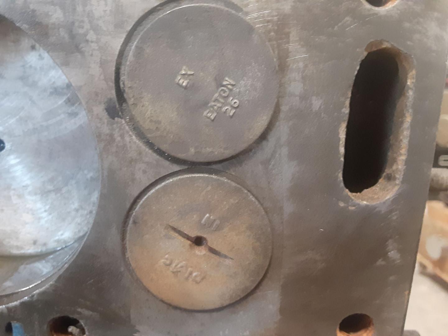
I have a mixture of PA and Eaton valves. The PA ones have a slot in them for a valve grinder.
Here is the grinder. You put the 1/2 moon blade in the slot and turn the handle and the grinder rotates clockwise and then automatically switches to counterclockwise.
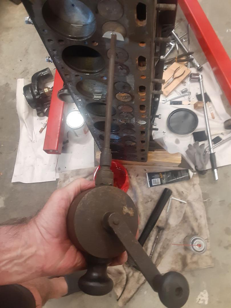
I am trying to fit the magnet setup to this grinder to do the valves that have no slot. The surface is too rough for a suction cup.
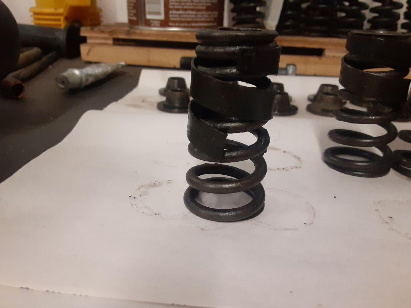
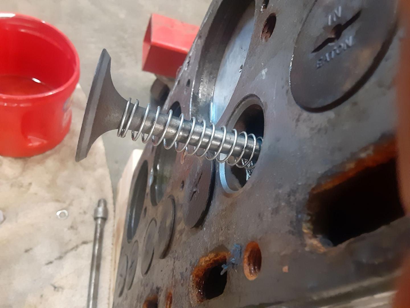
OK, does someone know what the purpose of the wound strip of steel around the valve spring is for, rigidity?
This spring is out of my ’35 engine, the ’33 ones were just straight. The small spring OD is at the top.
Bill,
The flat helix around the upper end of the spring in your picture is a damper and yes, you need to keep it. The reason for the damper is to prevent the spring going into “resonance” and breaking when the engine speed is at that exactly wrong speed. I expect that earlier years had more broken valve springs than expected, so this damper was likely the Pierce factory fix for your car. Dampers are still used in some racing engines to prevent resonance vibration and float at high speeds. Search for “valve spring damper” and look at the images; same concept but the flat coil is now inside of the helical spring. After cleanup, put your damper back on the spring and install this combination in the same orientation as found during removal. This damper works by friction and should be slightly snug around the valve, enough to touch it, but not restrict spring movement. The idea is to change the natural frequency of the spring, but not change the spring force in either the valve open or closed position. Hope this helps. Herb
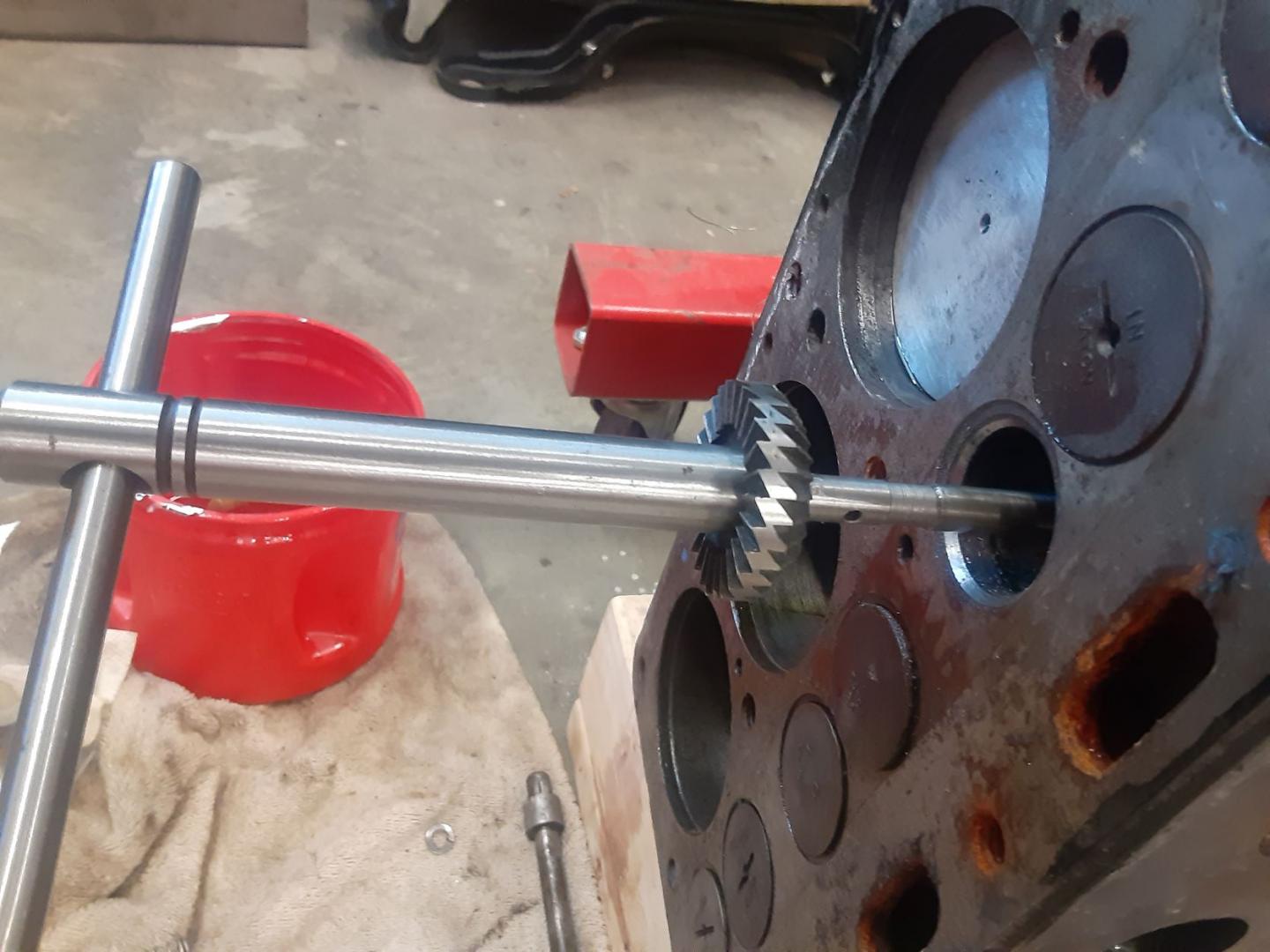
I had previously cut the seats but here is the tool for doing that. Pilot is the diameter of the valve stem.
This is the valve setup with the spring to lift it off the seat so you can spread the compound
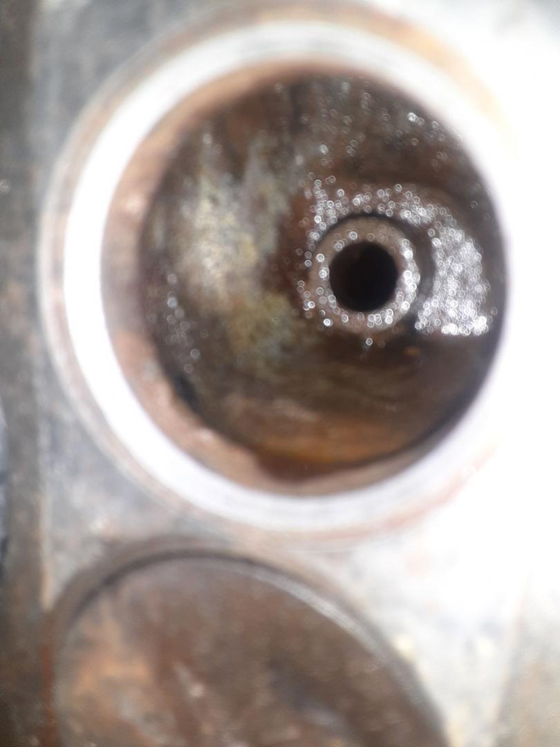
Gound seat.
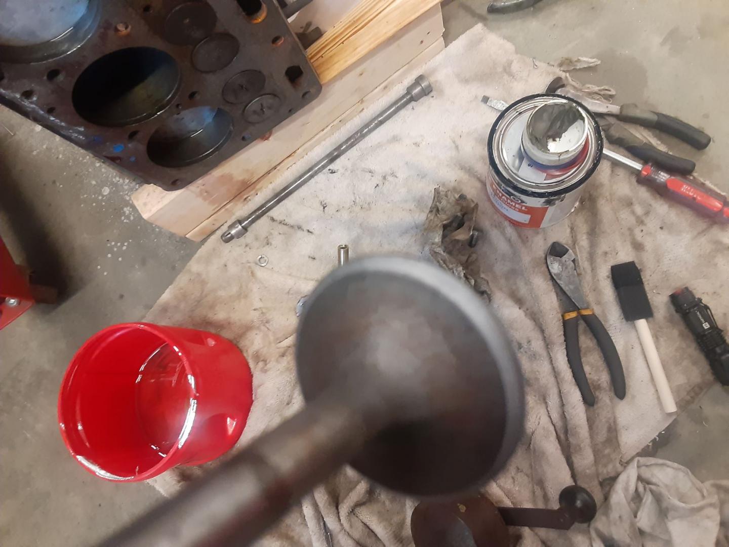
Ground valve
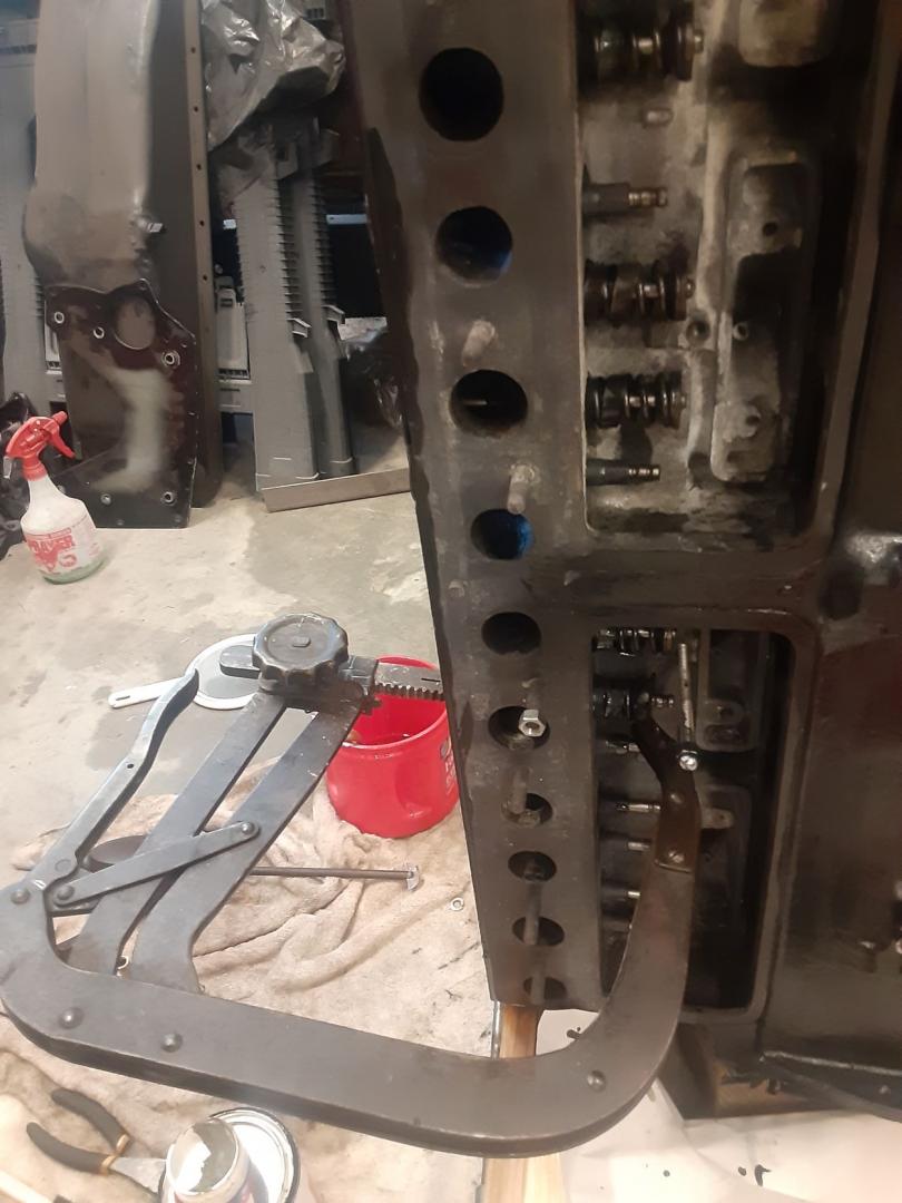
Spring compressor and installed valves.
I like the idea of the magnet, but attached to the valve lapping tool. When I was there I cut the suction cup off a modern hand tool and attached it to my valve lapper with a thin piece of flat stock put in the same slot as the original half moon.
I took a rubber stopper that fit into the intake/exhaust ports, drilled a hole in it and inserted a long nosed air gun in it.
The air pressure will expose a ill fitting valve, need soap or some liquid on the valves to see bubbles and worn guides.
I had a couple valves that had slight leaks that had to be reground.
Could probably use as a test on an unknown engine. Just turn to where the valves are closed, take off manifolds and insert the stopper, apply air and look/listen for leaks.
