- Home
- About Us
- Join/Renew
- Member Benefits
- Member Pages
- Log In
- Help
- Museum Store
Hello everyone !
During a recent recommissioning of an engine in a 1925 80, it became clear to us that the valve train of this engine had suffered damage to the rear lifter tray (part number c98 251). It looks as if it caused significant damage that had been repaired in the somewhat distant past.
The current concern is: how does this happen? And are there any sources for the rollers for the lifters, the lifters, and the lifter trays?
Thanks for your interest!
Douglas Nelson
Hello Douglas, Welcome to the Pierce Arrow Society.
The lifter trays are often damaged. And hopefully repaired before the roller on the lifter turns sideways and removes the lobe of the camshaft !
Lifter trays are being reproduced and sold by Karl Krouch. Look in the Emporium, Karl has an ad for the trays posted there. I have used these reproduced items and they are excellent.
What causes the damage is that a person adjusting the valves cannot hold the lifter body, this is the cylindrical part with the threads for the adjuster screw on one end and the slot and pin for the roller on the other.
The adjusting screw threads into the lifter body, and the lock nut jams against the lifter body, locking the threads of the screw against the threads in the lifter body. The friction, and jamming forces are between the lock nut and the lifter body. A person can only hold the adjusting screw, not the lifter body with a wrench. The lifter body twists from the turning of the jam nut, and the roller forces the slot in the tray wider until the ears on the sides of the slot break off.
What I’ve done in the past and recommended is to check the valve lash first on all the valves, noting and marking the ones that need adjusting. When the valve is closed, the lifter body is as low in the slot in the lifter tray as possible, in this position, any force on the roller has much more leverage on the ears, and therefore it takes less force to break the tray.
Then I rotate the engine until each lifter that needs adjustment is at the fully open or highest position in the tray. In this position it is more difficult to damage the tray if any force is exerted on the lifter body when loosening the jam-nut. A person must still hold the adjusting screw, and attempt to have NO rotating force applied to the lifter body. The same applies for tightening the jam-nut after adjusting the valve clearance.
I have devised a way to hold the lifter body, which I’ll show in the next message.
There are new pins and rollers available. I do not have any in stock at this time, but will be getting some in the next month or two.
Greg Long
Hi Douglas, here are some images of the lifter modifications I make on my series 80 engines.
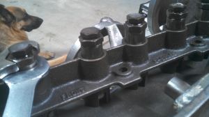
In this image you can see several un-modified lifters in the lifter tray as well as a modified one with wrenches showing how the lifter is held under the jam nut.
Sorry for the cameo-appearance of my dog LOKI.
Greg Long

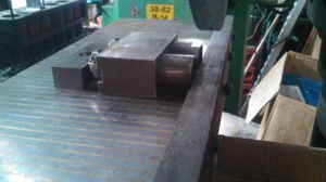
Here is an image of two of the lifter bodies on my surface grinder. I made a fixture to hold the lifters to the magnetic ‘chuck’ for grinding. The closest lifter is un-modified, the furthest has been ground, and is shown for illustration purposes.
The lifter body is made from very hard steel, and would be difficult if not impossible to accurately machine on the round end of the body. A surface grinder can take less than .001″ off per pass of the grinding wheel. This allows us to ‘machine’ or shape the very hard lifter body. And, since the ‘cut’ on each pass of the grinder wheel is such a small amount, the lifter can be held magnetically rather than having to be clamped to the work table.
Greg Long

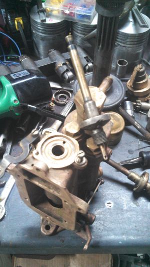
Here is an image with a broken and repaired lifter tray in the background. I’m sorry, I don’t have an image available right now that is just of a repaired lifter tray. I apologize for the cluttered image.
The repaired trays work well, but are probably easier to break a second time, and must be treated even more gently than an original undamaged one.
Greg Long

If you compare the location of the lifter roller in the last image to the position in the first image, you can see that if any rotational force was applied to the lifter when the roller is deeply seated in the slot, the tray is unlikely to be damaged. If the roller is near the end of the slot, the leverage applied would be much more likely to break the lifter tray.
Greg Long
