- Home
- About Us
- Join/Renew
- Member Benefits
- Member Pages
- Log In
- Help
- Museum Store
I am wondering if anyone can point me to a source for generator regulator information?
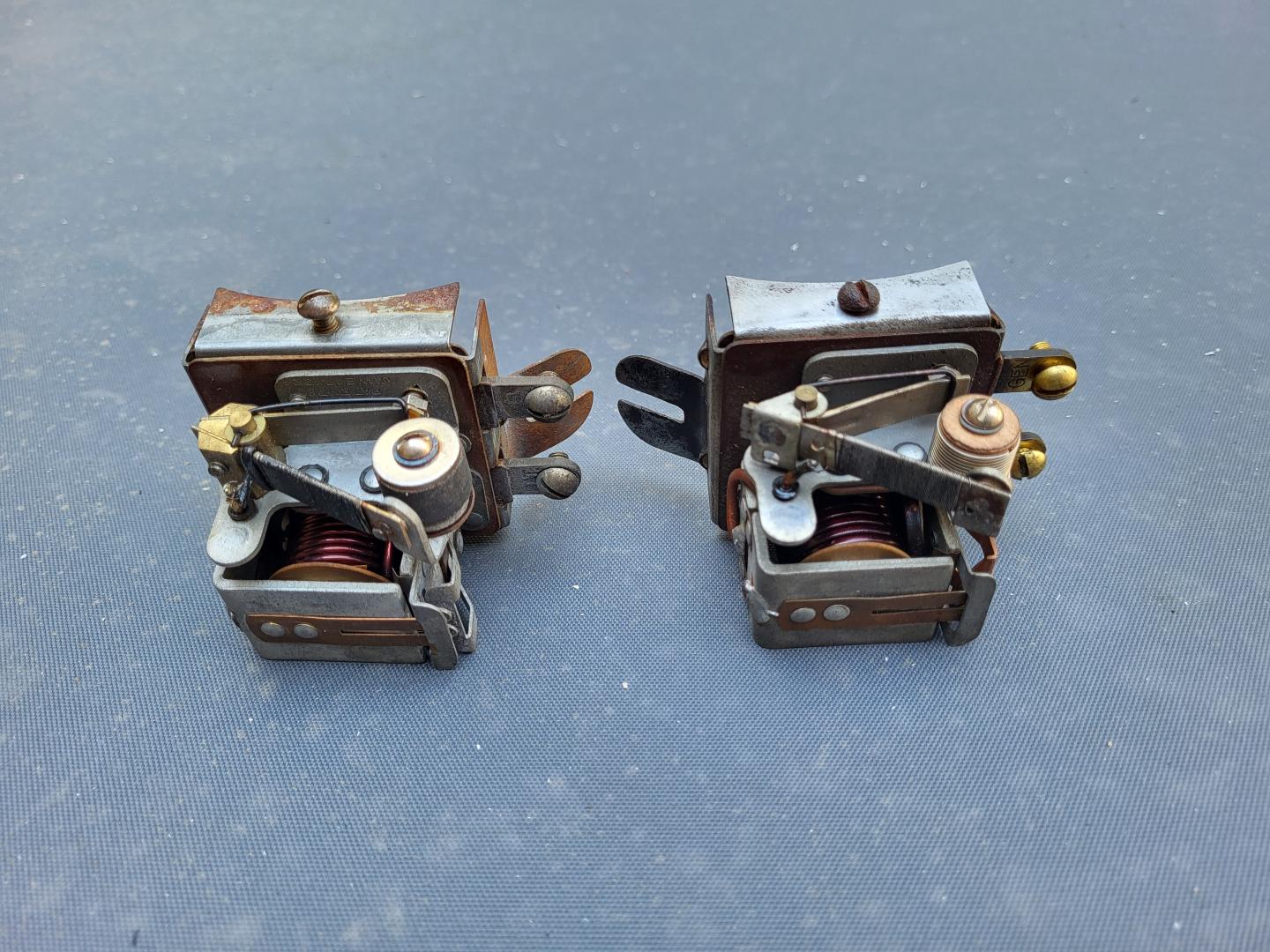
I managed to get the broken resistance wire for the bimetallic strip reconnected and now the generator is charging but not sure it is working right. This regulator is the same 21262 part number quoted in the wiring and tune-up guide for early ’35 845’s and used for several years on Packards. The left is off of a ’34 or ’35 Packard, on the right is off my ’35 845. One of the differences is the round resistor that controls field winding resistance when the bimetallic strip heats up and breaks contact. The Packard’s is a curious solid porous brass drum and reads less than 1 ohm resistance. The Pierce is wire wound on a wood core, and the wiring tuneup guide states it should be 2.15 ohms if I am interpreting things correctly. Testing the Packard regulator the resistance change is nill when the bimetallic strip contact opens.
I wonder if there is a manual for these regulators with specs, a guru who is an expert on them, or someone that can repair them?
I found this online and it was very helpful. I am not able to attach the entire manual. Try googling it. If you can’t find it, I can email it to you.
Robert
Robert
Robert,
If you can email it to me, I will see if I can get it up on the website.
Thanks, Dave
Dave,
Okay, I just emailed it to you.
Robert
So here’s my $.02 worth: According to my collection of old text books, both of these regulators are of the TIRREL type to control current in the field coils. These are the “vibrating” type where the contact is opened and closed very frequently to provide an “average” field voltage / current and thus control the armature voltage / current to the battery circuit. The full field current is provided when the contact on your regulator style is closed. When closed, it shorts around the resistor, greatly increasing field current and armature output. When the contact opens, the resistance is in the circuit, reducing the field current/magnetism available. The circuit shown on Pg 72 in the Pierce wiring guide book shows this regulator on the ground side of the field; the source of field voltage is the third brush.
The field resistance itself is very low; about 1 ohm in my generator after a fresh rewind. The residual magnetism and remaining small field current are enough to prevent motoring the generator while driving. In the Pierce version, this resistance is in the coil, as you have measured, and is removed from the circuit when the arm contact is closed onto the coil. The Packard version uses the external (wire wound) resister as the high resistance element in the circuit – which would require a very low resistance contact to apply full voltage to the field while shorting the resister out of the circuit, as you have measured.
Your test of the Pierce is correct for the coil resistance when the arm is lifted. On the Packard, the measurement would be across the wire wound resister, which should be about 2 ohms, matching about what you found on the Pierce. If there is no voltage at all, suspect a broken wire in the resister. Having the bimetallic arm contact provide more voltage to the low resistance field is correct for either resister placement. Regards, Herb
Herb, thanks for digging this up! I will be curious to look these up. I finally found another source, a Standard Auto Electricians Guide which covers most US auto electrical systems for 1927 to 1937 and has a good explanation of this regulator. It mentions the drum resistor which is a bit of a mystery. My Pierce unit on the right is the wire wound unit, the Packard on the left is solid. The guide states in 1933 the wire wound was replaced with a solid carbon unit. My Pierce is 1935 and Steve P.’s posts in 2021 with the identical two regulators also shows wire wound on Pierce and solid drum on Packard. According to the manual, the resistance of the newer solid style can be adjusted by changing the tightness of the mounting screw. I tried doing that but found little difference in resistance with screw tension, my ohmmeter dances between .8 and .9 ohm independent of tension. However, the guide says the drum is carbon, but it looks like sintered bronze to me, so maybe this was another change in the later Packard units. Curious that the Pierce 1935 unit apparently retained the older wire wound 2 years later, particularly since it looks like Pierce only used it for early 1935 models.
Another quirk is that the Pierce wiring and tuneup guide shows the regulator as a 21262, but the Guide says 21732 which is mentioned in other posts on this forum. The 21262 is listed in the Packard parts books for 1935 and several years prior, so may be less challenging to find.
The tension on the bimetallic control arm is much stiffer on the Packard unit, perhaps a misadjustment. The detail design of the bimetallic strips are different. Both of these regulators failed due to the connection of the very fine resistance wire breaking and had been repaired before. A very delicate soldering operation. I am thinking that to substitute a Packard regulator would require changing the resistor to get 2 ohms.
I’m hoping between the Autolite manual and the Auto Elecrrician Guide I can get this sorted out better.
By the way, several posts mention the extra “gen” connection for Startix on Packard regulators. Startix was an option on Packard and the ignition switch has two “on” positions, “regular” and Startix. I use the extra position to operate with or without electric fuel pump.
There is a link to the “Standard Auto Electrician’s Manual 1928 Through 1937” in the Parts and Services Directory under Service Manuals. You can also download a pdf file from that location.
That’s great! I didn’t realize the link was there. I wonder if it would make sense to add the links for these kinds of guides/manuals to the service and owners manual section? I see the general wiring tuneup guide has been added there. It didn’t occur to me to look in the parts/service directory spreadsheet.
Thanks! Jim
Hi Jim,
Yes, the Wiring/Tune up book just went up. The Company Store only has a few left that are unbound so it seemed like a good time to post it.
If someone wants a printed version, they can still get one.
It’s possible that the web folks could put the links on the Manuals page, I will have to check, or maybe a reference to the P&S Directory. The P&S Directory is just an Excel Spreadsheet and is really easy to add or change when links move or go bad. Easier than webpage modifications.
From the pictures I saw of it, it looks like your ’35 is complete.
Dave
Yes, a note to look for links under in the P&S directory would help. Also, in these cases a line in the P&S directory under “electrical” could help.
