- Home
- About Us
- Join/Renew
- Member Benefits
- Member Pages
- Log In
- Help
- Museum Store
I think the answer to my question is obvious, but I will ask it anyway. I am disassembling my generator now. It looks like the 2 arm fitting that drives the water pump shaft is held in with a press fit dowel and the only way to get this off is pressing it out? Any words of wisdom on just how nasty this is?
Also, my regulator/cutout actually appears to be in good shape, but I am wondering if there is a reliable solid state replacement that does a better job of not overcharging – or maybe the original works just fine? It looks like the ’34’s had a 3rd brush system that I am familiar with for reducing charge rate but my ’35 looks like a 2 brush without adjustment. A friend told me people would drive around with their headlights on in the day so they didn’t overcharge the battery. I know this was discussed many moons ago.
Thanks, Jim

Hi Jim, most often that dowel pin is a TAPERED steel pin. I usually carefully grind each end of the pin flush with the collar on the drive hub, then look closely and measure to see which end is the smaller diameter. You have to drive out , or press out the pin from the small end.
Greg Long
Hi Jim,
One note on solid state (diode) cutout replacements – I had a simple 25 amp diode cutout replacement fail in my ’34, and since the generator then had no load on its output, the voltage went up around 18 volts and blew the top solenoid in the Startix unit. Of course, the same thing could happen if a conventional cutout coil opened up, but I have never seen that happen. To avoid any future problems, I went back to a conventional cutout, and just to be safe, installed a fuse (I believe 2 amp) in the generator to Startix lead. My ’34 is a 3-brush system and has no problems with overcharging.
Bob
Jim,
Like Bob I had a diode failure on our ’33 1247 after thinking solid state would be more reliable. Fortunately caught it at the time because I was just driving around closely monitoring charging rate as I suspected a generator issue. We went back to the original type cutout, learned soon after that the starter was my problem low voltage problem. The cutout has been fine for the last 12 years since with lots of fun touring miles.
It’s interesting that Bob’s Startix failed that way as I’ve found them to be very reliable gadgets once you understand and have them set up correctly.
Dave
When in doubt, assume Pierce knew what it was doing. I’ll clean up the original regulator/cutout and use it as is. Now, to the struggle with tapered press fit dowels! One of the things I really don’t like doing, for fear of screwing something up badly (like my #1 hydraulic lifter – fingers crossed).
Thanks for the responses!
Jim
I love the way Greg described the process: “carefully grind………” Compare this to the process of a non-wrench,myself: “……Beat the …. out of both sides until the pin comes flying out”.
LOL, Tony, you spent your lifetime selling cars, right, or teaching your salesmen to sell them.
So, I’ll use a sales analogy: Find out what the buyer needs, and wants, and measure them for the
car, see if they will fit, and the car will do the job for the customer.
DON’T just corner the customer and beat them over the head with a sales contract for the most
expensive car on the lot !! 
Of course, I rarely tell HOW I learned some of my techniques I share: I have an archive of beat-up,
damaged parts from decades of mistakes. And an archive of memories of conversations with other
people sharing their mistakes, so I hopefully learn to not make the same mistakes.
Jim: a Dremel grinder with a cut-off wheel will shorten the protruding stubs of the tapered pin, Then you can
see or measure the pin to figure out which end is the narrower one.
If you can, post a good close up of the hub showing the pin,
Greg Long
Jim, I just looked at your photo on the first message in this thread. The end of the pin shown looks like the
large end of the pin, It is driven to just below the surface of the hub, I’m betting the other end of the pin protrudes from the hub and is mushroomed over a bit to keep it from backing out. If so, you’ll want to cut of or grind off the protuding/mushroomed end and drive or push the pin back toward the larger end of the hole.
Take a similar quality photo of the other side of the pin. I’m betting it is smaller than the side you show in the image, with a slightly mushroomed end.
Greg Long
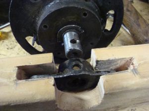
Greg, I cut a crude jig out of a piece of 2 x 4 to support the shaft without loading the bearing and got it started with my press. It tapped out the rest of the way without any drama (there is a hole drilled in the wood that is covered by the drive fitting that the pin goes into when it is being driven out).
Thanks again!
Jim

