- Home
- About Us
- Join/Renew
- Member Benefits
- Member Pages
- Log In
- Help
- Museum Store
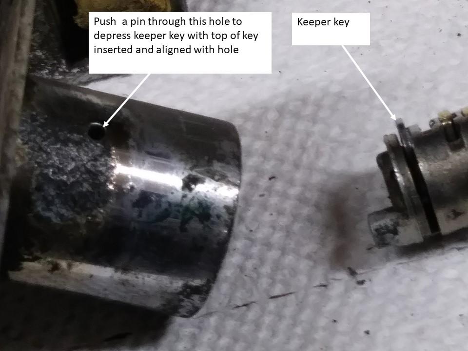
I don’t know if this helps for a door lock , this is from my trunk lock cylinder. The trick is to get the cylinder in the right position and insert a pin to depress the keeper key to pull out the cylinder. I fiddled with this for about an hour before I took it to a local locksmith. He fiddled with it for about 5 minutes and charged me $5.
I believe a gentleman had one installed on a huge ’36 Packard V12 7 passenger, but don’t know the detail.
My first worry is how absolutely fool proof and safe is the system. Can you realistically still steer and maintain control with any plausible system failure which includes simple override from electric failure to the more serious issue of a sudden uncommanded turn input.
This is similar to the scenario of the 737 Max pitchdown issue, and in aircraft world one of the most difficult problems to deal with.
I would want to understand the system better and see how this is addressed. Electronics have lots of gremlin potential. A friend of mine got rid of his modern car with steer by wire (all electric/electronic) steering because it gave him some brief uncommanded twitches on a 50 mph road.
Jim
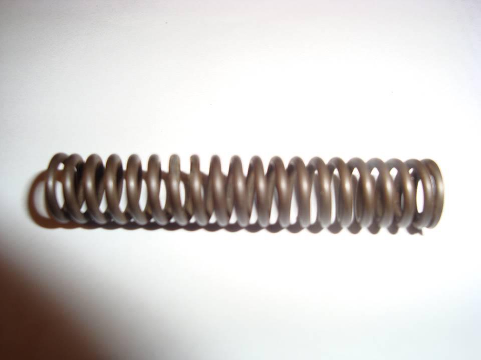
For what it is worth, I measured my 1935 845 original spring having a free length of 2.12″, OD .407″, wire .0615″ dia. I don’t know if it is the same for 1931, but you could check yours. The same spring was used 1933-’35 at least, part number 703795.
If it seems to be the same, I bought a pack of the closest facsimile I could find and have extras if you need one.
Hopefully someone will chime in with info on the ’31. 
Bill, PASB 84-1 says the squirt hole should be on the right side of the engine when viewed from behind.
Bill, I don’t have any pictures that show mine – not that it is right anyway. If I recall the rod has a squirt hole for cylinder lubrication on each and it is symmetrical. If so it shouldn’t matter the orientation of the rod as long as the skirt slot is on the correct side, that should be noted in the PASB’s.
A huge sight, shows several more seventies and eighties movies the Tom Sparks 845 was in that I haven’t seen.
Looks like a very clean fender to work with, nice!
Bill, I like to get inside bevel rings for the top compression instead of plain for better oil control. I had a hard time finding 3.5″ 1/8 with chrome face for mine, but finally found them at Grants. I was able to order them individually instead of a set. Taper face are easier to find, and are usually considered better oil control than plain. My Packard has chrome taper face with 30000 miles.
I have used the type 70 scrapers for 2 and 3 as per original and 3 segment chrome face oil control.
I just have one side in pretty rough shape.
Jim
My block didn’t have rust issues and to flush the galleries I bought a 12v high volume/high pressure fuel pump and filter and attached a long tube to pump kerosene. I had the oil pan underneath the block to catch and recycle the kerosene. I smelled pretty bad that day.
McMaster should have the LH tap and bolts.
Good thing you checked! Does that mean they cut the crank down .040?
There are small springs that control the two centrifugal flyweights under the plate that holds the points. Substituting weaker springs will provide more advance with rpm. If everything else is up to snuff the difference shouldn’t be too noticeable, a very slight increase in power and wouldn’t correct a miss, unless one of the springs is broken or missing.
The first time my Packard quit charging (with basically the same 3rd brush setup and regulator as Pierce) it was the regulator, the second time a few years ago it was simply the 3rd brush was worn out. They are easier to find than regulators if that is the case.
If I remember right it was a bit iffy to diagnose statically, testing it would show continuity statically. Good luck.
Yes, cerrosafe alloy block from McMaster. Pretty strange working with a bright metal that melts below 200. Keep thinking I’ll get scalded.
Extrusion is from Mac’s, same one is available from Snyder’s. Look out for shipping charges, can be more expensive than the pieces and gets tacked on per piece.
For many years NAPA sold a regulator VR755 that was used by many mid ’30’s classics as a universal substitute for the wide range of regulators used on those cars. It mounts to the generator as original. Unfortunately they stopped producing them a few years ago and they are very hard to find now – a lot of people bought spares. That specific regulator was originally used on some models of ’35-36 Chrysler products. It does not have the extra gen lead sticking out the side to connect the startix (it was optional on Packard), but the gen connection is made under the regulator so I think the extra connection could be made there. I have a generator with regulator from a ’33 or ’34 Packard that looks identical to my ’35 Pierce unit including the hookups, although the internals are actually a bit different. It would probably work, but much harder to find than VR755.
The picture is one I took of a ’36 Pierce which appears to have a NAPA VR755 regulator attached to the top of the generator, the tell tale being the nut on top of the can.
Bill, I don’t have any direct experience with cracked blocks, so not sure. The location and direction of the crack is a bit puzzling to me, but it seems it might be a combination of over stress from over torqueing the nearby stud and stress corrosion. Apparently the surface has a a high tensile stress left to right around the stress concentration of the hole and a lot of corrosion. As the crack starts it generates a very high stress concentration at the leading edge of the crack that exposes more virgin metal to corrosion and lets the crack grow more. My first thought is to stop drill only with a pretty small hole and without a tapered pin. The tapered pin would increase the local tension stress at the crack stopper hole. Maybe that’s a good thing to yield material locally around the hole to reduce fatigue, but can’t sort it out in my head at the moment. I might use a bit lower than recommended bolt torque for that stud when installing the head.
Jim
I am unclear about what the status of this forum is vis a vis the AACA forum. In places the names of the posters are not included, I assume these had some involvement on the AACA sight?
After the glitch was diagnosed and apparently fixed, was it decided to wait a bit to make sure it was fixed before deciding whether to go with it or stay independent?
Personally Covid has allowed more time to concentrate on restoration, and I am quite unsociable anyway. But I imagine those with driveable cars who are more involved with shows and tours just aren’t too engaged at the moment.
My posts are primarily involved in restoration, and I have the perception that only a small portion of members are actually involved in hands-on restoration anymore.
I apologize for not responding sooner, low oil pressure on a fresh engine always a concern. I would expect the engine to go up to over 20 psi fairly quickly when started cold. After it gets hot very low oil pressures are not necessarily a problem. My Packard after rebuild 30,000+ miles ago has always barely registered at hot idle, goes to 35 or so on the road. My ’74 Alfa has 170,00+ miles and it’s hot idle reading has always been so low it basically doesn’t register on the gauge and decades ago I confirmed with a separate mechanical gauge that it really was above the 2 psi that would light the low oil pressure warning light. Before it’s rebuild at 99,000 miles (with hardly any wear and no issues when torn down) I discovered a crankshaft oil gallery plug had blown out. After rebuild it hardly read any higher. That may be because often the new inserts (not relevant to P-A) can have more clearance than the originals. I theorize that bearing suppliers may be worried about liability exposure if a customer rebuilds an engine too tight and it seizes, which is much more likely than any failure from higher clearance.
2 days ago I fired my ’35 Pierce up with an original gauge installed on the dash and was surprised it jumped to over 50 psi where the newer mechanical gauge I had been using mounted directly on the oil port never read above 40. I don’t think either of these gauges are paragons of accuracy.
What is your gauge reading cold at low idle and higher rpm when it reaches a steady point?
If it is reading zero that of course is a big immediate concern. If just reading low then there are a number of possibilities. The main thing is that oil is circulating, the oil pressure you read on the gauge is just an indicator that oil is circulating, and the ability of the bearings and pistons to ride the oil film without grinding directly on the sliding surfaces has basically nothing to do with the oil pressure reading as long as the oil reaches the bearing or cylinder wall. Oil pressure is an indicator that the oil is pumping and and reaching the places it needs to go. Note that many inexpensive low performance engines don’t even have an oil pump and rely only on oil splashing around.
Low oil pressure can be from several sources besides the gauge. The oil pressure regulator could be set up with too low a spring pressure to bypass oil sooner at high rpm. This shouldn’t be an issue at idle as the spring should be preventing any oil from bypassing. Another is the oil pump is significantly worn. The oil pump intake screen could be plugged with debris.
The most common cause of low oil pressure is excessive clearance in the main, con rod, and cam bearings, usually from wear. The whole oil system is like a sprinkler hose getting fed water with lots of little holes for the water to stream out of. If the holes -represented by the bearing clearances – are consistent and even then the all the holes will stream the same amount of water. If one of the holes gets a lot bigger than the others for some reason, then more water will flow to that hole and less will reach the other holes. If the wear in the bearings is reasonably consistent throughout then the lower pressure needed to get oil everywhere needed is not a big issue. If it is because of some major failure at some point then that is something different of course.
Thanks for the responses. Digging through my boxes – looking for something else – I came across the remains of the rubber flex oil line that was on the car in 1964, probably original. When I inventoried my boxes decades ago I didn’t know what it was and for some reason didn’t record it on my spreadsheet with a description that came up with my key word search. Getting a car with lots of boxes means many parts that you don’t know what they are, I still have a few of those and I will probably post some pictures at some point. Meanwhile I found a flex oil line to bridge between the engine fitting and the copper line going through the firewall at McMaster Carr and have an original gauge set up and working.
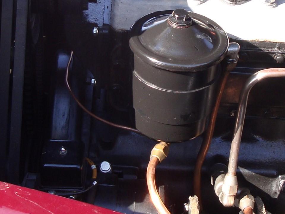
On my ’36 Packard, which has a very flexible 3 point rubber suspension system (Chrysler patent), the oil pressure line is smaller gauge 1/8″ copper line with several spiral turns above the fitting to allow for the flex instead of rubber.
Thanks again!
Jim
Thanks Tony. Well, the Pierce has 10 more hp and the original 4.23 rear end ratio so it should inch past the Packard uphill. But, my Packard has a 3.58 rear end and copper lead bearings, so better at higher speeds. Pierce would be better for those wine tastings tour stops, where one is stopped on steep upgrades waiting for everyone ahead to back into parking spots. A real clutch burner with a tall rear end!
