- Home
- About Us
- Join/Renew
- Member Benefits
- Member Pages
- Log In
- Help
- Museum Store
An additional thought on the pictures of Greg’s rods. Thick babbitt does not have high fatigue strength particularly at high temperature. It could be that the failure did not need to be from a complete breakdown of the oil film, but simply fatigue from the high stresses in the babbitt from the high gas load of the piston.
Jim
Greg, your pictures look like poster children for one of the problems/worries on P-A con rod bearings. Studebaker engineer Sparrow in 1935 “Problems in the Development of a High Speed Engine” noted:”The first rods had babbitt flanges on the sides and cracks in the bearing surface proper would frequently extend to these flanges and cause large pieces to fall out. This would permit the cracks in the remainder to spread and bearing failure would soon follow. Considerable improvement resulted from the elimination of the babbitt flanges and a further improvement from the adoption of the copper lead liners.”
In a previous 1934 report on bearings Sparrow also noted that at the high speeds he was testing (4500 rpm) cracks would appear first at angles of about 45 degrees off center in the cap that corresponded with the point where the load on the rod switched from tension to compression (gas load on the piston versus the centrifugal force in the opposite direction due to the inertia of piston and rod). He theorized that at high speed this is where the oil film might break down as the rod shifts slightly with the change in direction (SAE 34009).
The rods you show above look like a failure initiated near or at the side flanges at top dead center which corresponds with where the oil film would be most likely to break down under conditions of low rpm and high throttle when the gas pressure would be near maximum pushing down the rod with little inertia force acting opposite. This would be from low speed lugging.
I am sure that there are definite thermal expansion issues with thick babbitt. That would probably manifest as fatigue cracking added to the cyclic fatigue of the reciprocating loads. The thermal expansion would primarily be a function of hot and cold cycles (cold start/run/shutdown cycles).
Babbitt – like concrete – apparently always develops cracks. One of Sparrows comments on a set of his tests (he undercut portions of the babbitt surface to extend life) was “The cracks are slightly more numerous in the bearings with the undercut edges, but the undercut portion has served to as a barrier to prevent the cracks from spreading and permitting the babbitt to escape. As a result, although these bearings are marked by lines of ‘worry and care’ they are still serviceable”.
Jim
Back to the original question of how long it lasts and things to look for. One of the wear issues on 1930’s Pierce-Arrows is the ball bearing spring shackles system. Since I never drove my 845 in an “as-is” condition I don’t know if mine would have given any noticeable problems when driving, but they had definite wear issues. Others with actual experience driving them might be able to chime in here. Rechecking my original speedometer it was parked in 1948 with ~59000 miles.
The ball bearings of the upper hangers and shackles had pounded significant indentions into the pin races on the loaded side. The exception was the fwd end of the rear spring hangers that has larger diameter pins and balls. The aft bottom shackles of the front springs were complete toast – corrosion severe enough to literally turn many of the balls into red dust. I suspect this was more to do with sitting for decades with salty water in them. Before being retired this car would have been driven on salted Wisconsin roads in winter/spring and those shackles would be the most exposed to slush and water kicked up by the tires.
As I said, I don’t know to what extent the level of indention would have effected the noise or handling of the car.
Jim
Luke, I am unaware of a characteristic of babbitt just failing because of just sitting around for decades protected in a more or less closed crankcase but I am no expert on the chemistry of babbitt. I do have the feeling that babbitt failing just from old age is an urban legend based on theorizing about failures that occurred for other reasons, but would be happy to be pointed to an authoritative reference that shows otherwise. Perhaps someone has some reference data on this. I can imagine there could be chemical reactions generated by acids or water in the the oil that could effect the babbitt in some sort of corrosive process. Perhaps there is some extremely slow reaction that occurs with age. I can’t claim to know but would like to.
My personal experience is with copper lead inserts which is of course not spot on here. My ’36 Packard sat in a Massachussets junkyard with very serious rust/rot exposure from the late ’40’s to late ’70’s. New inserts for rebuild have long been a big problem for senior ’30’s Packards, but my inserts were in surprisingly good shape. My crankpins, however, were worn .004 out of round from the new (in 1934) harder copper lead insert material. I had the crank hard-chromed back to standard and used the original inserts. They had 56000 miles in its first life, they are 82 years old and still in the car with something over 25000 more miles of hard driving (including lots of 65+mph on the interstates). I have been more worried about the crank cracking from the hard-chrome stress concentration in the crank cheeks than from the bearings failing. Of course the cam and main bearings on my Packard are babbitt and just as old and have not failed yet either. They aren’t as highly loaded or run as fast as the con rods of course.
I guess by not spending anything close to $25000 on the rebuild it was supposed to fly apart a long time ago.
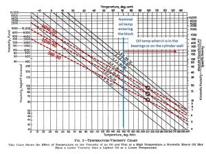
I have always used 10W-40 in the Packard but recently switched to 5W-30 after thinking about the 845 Pierce and keeping its babbitt bearings alive without overdrive or a high speed rear end. The 845 has the additional complication of keeping the hydraulic lifters quiet at idle if the oil gets too thin. A 5W-30 oil has the advantage of being thicker than straight 30 or 40 when the oil film in the bearings or on the cylinder wall goes over 250 degrees locally while the bulk of the oil is still at crankcase temperature. The oil temperature regulator on ’30’s Pierce and Packard’s was an addition that basically tried to control viscosity the way multi-vis oils later did.
The chart is from a 1930’s SAE report on the oil temp regulator with my approximations of multi-vis oils spotted on.
Jim

Scott, you might want to contact Lynn Kissel regarding vapor lock on 12’s. He has a beautifully restored ’33 (he took first in class at Rohnert Park) that has had problems with vapor lock. He installed thermocouples and tracked what temperatures and conditions will bring the onset of vapor lock (I wonder if he got any deductions for his thermocouple leads?). He also installed a clever fuel vapor return system to alleviate the problem. In my articles I mentioned that I didn’t think a fuel recirculation/return system would likely benefit vapor lock partly because the recirculating fuel would heat the fuel in the tank. Lynn’s system is designed to separate the vapor at the carburetor and return only vapor to the tank. That could mitigate much of the heat gain problem.
Jim
Bill, thanks and great work. I find this part a bit fun because in my former life I did aircraft surface loft design and generation. Getting a fair loft curve is tricky. To get the vertical profile I ran a datum string line from front to back under the left side sheet metal and measured distances to the string at 6″ intervals then smoothed the curve results on a CAD program and translated the dimensions onto the wood.
I haven’t cut my bows yet, but the measurements on my 845 club seem to indicate that they were all a constant radius from front to back, so I can use the cut from the first to do the rest and just change length. I suspect the factory might have steam bent them all in a single tool and cut to different lengths.
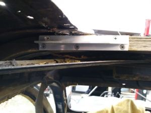
I am planning to use a different option for attaching the bows to get around the retrofit problem of the original mortise and tenon with the longerons already installed. To attach my Packard bows years ago I simply routed pockets into the top of the longerons and mating cuts into the bottom of the bows, but it bugged me that method weakens the structure of both longeron and bow. Jack Guyomar had suggested using a biscuit, and chewing on that thought I came up with the alternative of using 6061-T6 aluminum TEE extrusions – 1″ width with 1″ leg instead of the biscuit. I can screw them into the sides of the longerons and slot the bows. I can then screw through the bows and leg of the tee and lose less strength – admittedly this is gilding the lily structurally, since simply eliminating the finger joints makes the longerons much stronger than original.
I am also using that tee extrusion to attach the front of the longerons to the front rib/bow that is still solid and I didn’t need to replace. The original wood screw attachment is completely inaccessible under the skin. The tee extrusion does double duty to splice across one of the front bow/ribs finger joints that I would have to destroy to find out if it is still good.
Obviously this isn’t how the factory did it – that would require cutting the steel body panels off, rebuilding the wood frame then rewelding/releading the body panels. Since restore means to return to a previous condition, I guess my method is more a local repair rather than a restoration.
This also shows I am using incorrect for the period phillips head screws for the repairs – I’m not trying to pretend this is as original. I could have created something that looked original from surface appearance with very poor structural integrity.
Jim

Well, since we are sharing pictures, I am also in the midst of replacing the top picture frame and bows. I am using white ash, it is easy to get mailorder from woodworkerssource.com. I think ash is less prone to splitting than oak. When I did my Packard 35 years ago I switched midway in the restoration from ash to maple as it was more available locally and I preferred it best for working without splitting – all of those countersunk wood screws.
Packards were originally white ash, not sure about Pierce. A Packard expert waxed poetic about the superiority of ash for car bodies, however my dad, who had been in the sawmill industry in Wisconsin said it probably had more to due with the availability of ash in the midwest at that time.
I have been stalled for two weeks before installing the picture frame as I found hidden rot in the driver side longeron below the picture frame that is part of the primary structure keeping the top of the “B”” pillar in place. I am finishing up that repair today.
Jim”
Bill, that is an interesting source I hadn’t seen before. They do make a black leather covered strap that has the right dimensions and much less expensive than Steele.
Thanks!
Jim
I can’t speak to the operation since I am only to the point of being able to run mine in and out of the garage – although I am pleased with a system that stops as well going in reverse as it does forward!
In terms of longevity, my 845 apparently had 55000 miles when it was retired and left to sit after WWII. When I dissassembled the power brake unit the soft woven clutch material appeared to have no wear, was in good shape and I just put it back in. There was a spot of very minor surface rust in one area of one of the pressure plates that I easily removed with very fine sandpaper to match the original surface finish. I think the key to longevity was maintaining transmission oil in the system that keeps the liner wet and lubricated. I imagine the most likely problem is leakage of the seals around the brake output shaft that would drain the transmission. The many PASB messages over the years seem to indicate the friction characteristics of the clutch material are very important to how the unit performs including whether it wants to creep at a stop. For this reason I was relieved that mine seemed to be in excellent shape and didn’t need replacement with some other material which inevitably will behave differently to some degree. If the liner is shot of course, one has no choice.
If the pressure plate faces are damaged, I would expect that turning them accurately flat and replicating the original surface finish would be very important. Theoretically speaking, too course a finish would tear up the liner quickly and too smooth might reduce the braking power.
Jim
Since Evaporust also makes a related product specifically marketed for cooling systems called Thermocure ,why not run it? I recently used it to run through my ’35 P-A to clear up the last of the rust that didn’t come out from flushing with a swimming pool pump/filter. I think the active ingredient is the same, perhaps the product is the same also, just different packaging or perhaps concentration.
Jim
I have three cars without a front plate, the only one I had a problem with is a 74 Alfa that is my everyday driver and it is only an issue if I park at a meter on the street where a meter maid can give a ticket so I avoid street parking. I figure the ticket is less than the cost of manufacturing a front plate bracket where there never was one. I do keep the front plate in the car in case.
Jim
Paul, did you have a chance to take pictures of your 845 original fuel line routing?
Thanks, Jim
Oivind, thanks for flipping the picture!
Is there anything new to report on the new top material after Hershey? Is it now available?
Jim
The car is in Minnesota.
The chart with the Studebaker engine.
Yes, it is a simple formula that doesn’t say anything about how a 250 cu in engine would produce 160 hp, although engines were doing that in the 1960’s via higher compression, better breathing, overhead valves, etc.
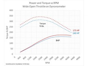
In this case my note at the bottom caused more confusion.I have dyno data for a 1935 Studebaker 250 cu inch engine which had eight cylinders of 3 1/6″ bore and 4 1/4″ stroke, that is 31.3 cu in/cylinder, 250 cu in for all eight. The Pierce 429 cu in 12 had twelve cylinders of 3 3/8 bore x 4″ stroke, 35.8 cu in/cylinder, x 12 = 429 total cu in. The 462 was bored out to 3 1/2″ with the same 4″ stroke to get 462 total cu inches.
Engines of similar era – downdraft carburetion, 5 to 6 compression ratio’s, etc would have similar power vs speed characteristics, so I simply scaled the 110 peak hp of the Studebaker engine to match the 160 hp claimed by P-A (a factor of 1.46). The friction and breathing of an engine is basically a function of piston speed, which is rpm x stroke, with the V-12’s having a slightly shorter stroke than the Studebaker, so I also scaled the RPM slightly to get the peak hp levels of the V-12’s to occur at 3400 RPM per the ratings stated in the Pierce spec sheets. The resulting torque was calculated and plotted at each hp/rpm combination.
It would be interesting to actually have dyno data on a Pierce engine, but I don’t, so I think this is a reasonable approximation.
I have added the Studebaker to the same chart for comparison.
Jim
Here is the chart with less confusing labels.
Jim
My labeling on the chart is probably misleading. The labels for “160 HP” and “175 HP” were just meant to convey the version of the engine, not that they were producing that HP anywhere except at the peak of the hp curve.
Jim
Just for fun I generated an approximation of what I think a power and torque diagram would look like for the Pierce V-12’s by scaling dynamometer data I have from a 1935 engine of similar bore and stroke to the P-A V-12.
Jim

Peter,
Torque in ft-lbs = HP(33000 ft-lbs/min-bhp)/(2 x pi * RPM).
Our torque estimates come out the same if you assume 160 hp @ 2300 RPM, but peak hp is stated at 3400 rpm. Power is basically torque x RPM, but max torque drops off as the RPM goes up due to increased engine friction and poorer breathing. At wide open throttle the engine producing 160 hp at 3400 rpm would be producing less than 120 hp at 2300 rpm.
Jim
