- Home
- About Us
- Join/Renew
- Member Benefits
- Member Pages
- Log In
- Help
- Museum Store
David and Tom,
It works out that the ’30 cars is a little less than 1.5″ longer with 159.5″ vs the 148.5″ on the ’33.
I guess that is to compensate for the Cobra Head?
Interesting. Thanks for the help.
Bill
Don,
Thanks for the offer, I will take you you up on it.
Sate safe and thanks again.
Bill
David,
Ah the Holy Grail.
Thanks for taking the time.
Bill
Tom Barrett advised that the ’30 Parts book lists the spark plug wire lengths, but he has, thru unfortunate circumstances’, loss access to his copy.
Does anyone have a copy and if so could they either list the lengths 1-8, or scan a copy?
Thanks
Just by chance, does anyone have the length of the individual distributor to spark plug leads?
Parts book says 148 1/2″ of cable but not the individual lengths.
I can puzzle it out, but was hoping for a short cut. Lazy I guess.
An additional 37″ coil to distributor is stated in the parts book, so I figured that one out.
Grommets for the individual wires I got from Harbor Freight for less than $5
Harness Grommet Set, 180 Pc. (harborfreight.com)
Robert,
You might try Coker if you get stuck. They advertise a 20″ lock rim, so maybe they can do a 19″?
As they advertise
“We hand-craft rims for antique and brass era vehicles right in our own machine shop. Impossibly rare restorations depend on our expert craftsmen to recreate authentic steel rims as well as the wood wheels that came on these priceless automobiles. “
Good luck
Bill,
Thanks for your help.
Bill
Kirby,
Wow, that looks great.
Good luck with the rest.
Bill
Ok, here is a McMaster-Carr fix. Part 96005217. It is listed as a 1 3/8″ hole, but the ID is 1″
After a couple of failed measurement attempts I was able to find a 1″ ID grommet for 1/16″ sheet metal.
With much coaxing, prodding and levering, along with some words from the dark part of my vocabulary, I was able to get the grommet in the oval opening.
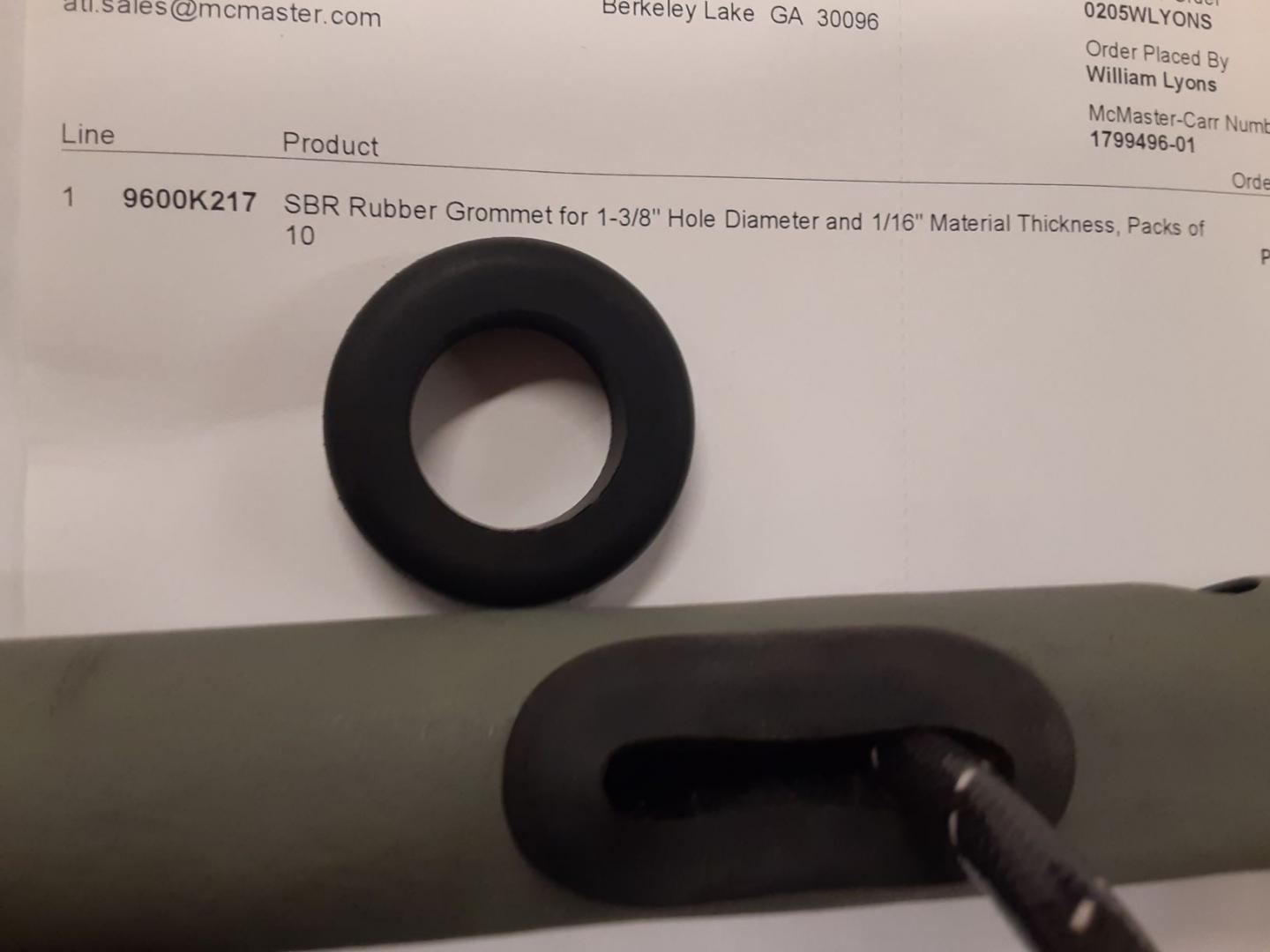
The plug wires are a tight fit but you can trim the slot a little if needed. It is heavier than the original and I might try the next size down but this eliminates the raw edges for about $1 per opening.
Mark,
That is great. Thanks for the help.
I will let you know how it turns out.
Bill
Jim,
Thanks for coming to the rescue. Another issue I am struggling with is the oval grommet in the spark plug wiring tube. If you look above the #4
you can see the 4 wires entering the conduit. Can’t seem to find an appropriate grommet for that hole.
Bill
All the rods and pistons are assembled. I went back and measured the width of the slot in the rod.
At the big end side it measured .133″ and at the pin end measured .129. There goes your pin clearance.
I started cleaning out the smaller galleries. I started with a .25 caliber gun brush and that did nothing. Move up to a .30/.32 and that seems the correct size.
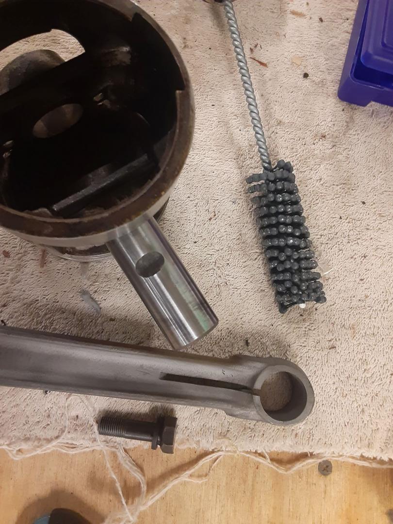
I have been struggling with getting the piston pins and pinch bolts installed in the rods. It is a push fit for the pin in the piston, but I couldn’t get the pin to turn in the rod so I could line up the notch machined in the pin that locks it to the rod with a bolt that “pinches” the pin on the rod. I tried heating the rod end and freezing the pin. By the time I got the pin in the one side of the piston, thru the rod, in the other side of the piston and tried to install the pinch bolt, things cooled or heated up to the extent it locked the pin in the rod.
I started to do some measurements. An old motor article which has just about all the clearances for just about anything on any car in the 30’s. It listed the PA pin at 15/16″.(.9375).
I mic’d mine at .9465. I then mic’d the bore of the rod and got .945 in the 3-9 o’clock axis and .947 in the 12-6 axis. Just enough to prevent turning the pin in the rod. Evidently the pinch bolt becomes oval when released. So close but so far.
I also had some burrs on the end of the pin hole so I bought a 15/16, 320 grit flex-hone and ran it thru the pin hole about 5 strokes and checked for pin fit. After about 3 cycles I was able to get a push fit on the pin and was able to rotate it. I assembled the pin, rod and piston and was able to rotate the pin so I could get the bolt in. Tightened it up and its ready do go.
Dave,
Thank you for the kind words. I enjoy hearing about people with operational cars, but for the moment I don’t have that.
I have bead blasted the valves. I have an assortment of PMC and Eaton valves and picked out the best from the ’33 and the ’35.
The ’33 has the lowest miles and I think the valves were the original PMC ones. All the Eaton ones came from the ’35 so I don’t know if that tells a story or not.
The interesting think about the valves is the slot in the head of them. It allows for a tool to be inserted to grind the valves.
The egg beater looking thing is a valve oscillator.
You put a light spring on the valve stem then insert the valve in the guide with grinding past on the face.
The spring allows you to lift the valve and redistribute the paste.
You insert the spade blade on the beater into the slot in the valve and start turning the handle.
It is geared so that as you turn the handle it automatically oscillates the valve clockwise then counter clockwise.
Saves having to use the sticks with rubber cups that you have to use the spinning between the hands fire starting skills from Boy Scout days.
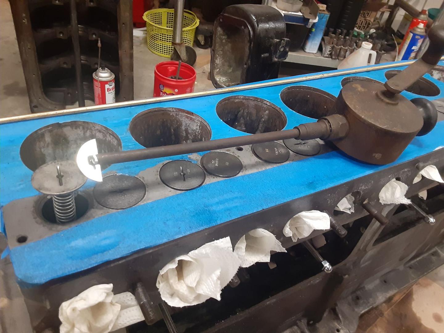
Still have a couple with out the slots that I will have to do the fire starting wafy.
I have resisted trying to drill out the channels as they are long and if you broke a drill off in them, you are in for a struggle.
I have found the long drill bits tend to break easier than smaller ones.
Don’t ask me how I know.
I am sticking with the brushes and derusting solution.
Put #6 in, alignment was good. I was looking to get the channel from the oil gallery to the #6 cam bearing cleaned so I took off the right angle fitting at the back of the block and it was completely blocked as was the channel to the #6 cam journal. This block had been hot tanked the old way about 30+ years ago, but I had it retanked after it was surfaced. Notice the rust coming out of the block. That thing in my hand is the right angle fitting that I just took off the block. No oil going thru that baby. I had to drill thru all the junk blocking the gallery.
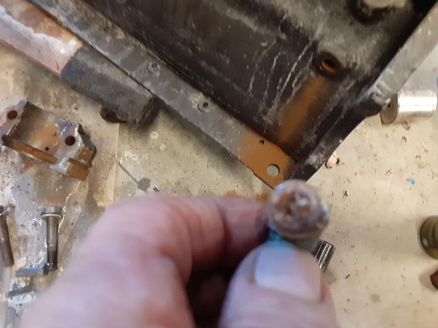
I guess the lesson is don’t trust that your galleries are good unless you personally check them. The channel to the cam bearing appears to be between 1/4 and 5/16 so I ordered a bore brush that will do .30 caliber up to 8 mm.
Jim,
I haven’t tested them yet. Planning ahead, just in case I have a problem.
They are like the ones that came out of my ’33.
Bill
Cam bearing are all out and was able to save the end plug. #6 cam bearing, which is the one at the rear has an oil hole that you have to line up but it is located at 9 o’clock looking forwards, not at 6.
I ordered a couple gun cleaning kits to clean out the oil galleries. The main one runs down the water jacket side of the block and feeds all the cam bearings. I had to order 2 kits to get enough of the treaded together rods to go the total length of the block. This kit is for 20 and 12 ga shotguns.

Here is the assembled rod laying on top of the block below the valves.
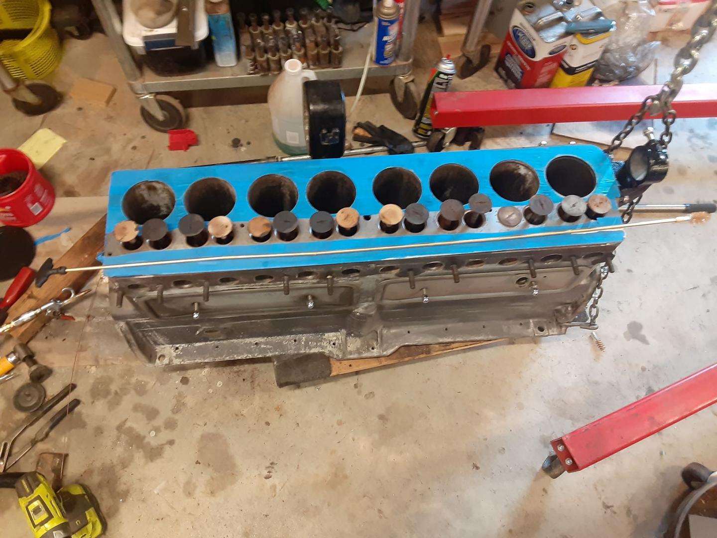
I started with the 20ga as it measured the closest to the galley bore. Then followed up with the 12ga. I got a lot of rusty dust and debris. This is the front of the gallery.

Rear of gallery
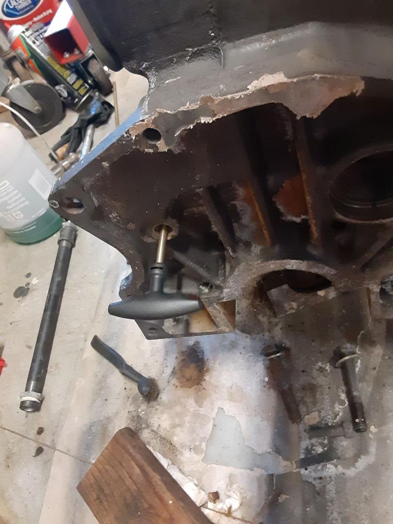
I will use the white swabs and use some sort of rust remover to get the gallery clean. Then I will run my endoscope down it to make sure there is nothing left.
Next is the side galleries that go to the bearings.
That will take a different brush, but the nice thing about gun cleaning brushes is they go from .17 or so on up so you can get a very close match to the gallery size.
Ok, I am anticipating the worse case scenario since I can’t use the Cadillac inserts.
That would be I have defective plungers that are not repairable and John C. doesn’t have any either.
I have a set of ’32 adjustable tappets. Any reason I can’t use them?
Thanks in advance.
Bill
